41 radar system block diagram
-- Figure 3-11: Radar System Block Diagram -- Receiver Transmitter The receiver transmitter contains all of the circuitry to gener-ate the RF pulse and to listen for its return. It sends this data to the display in many different ways, depending on the system.-- Figure 3-12: Figure 6: Ranging with a FMCW system Figure 4: Schematic diagram of a CW Doppler- Radar Figure 5: Speed gaughe "Traffipax SpeedoPhot " (ROBOT Visual Systems GmbH) Block Diagram of an CW-Radar Simple CW Doppler- Radar sets have a design shown in Figure 5. The generator generates very stable RF-Frequency f s. A second generator
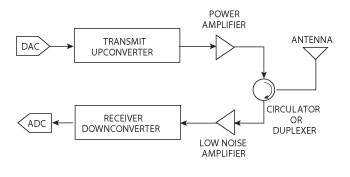
Radar Block Diagram • This receiver is a superheterodyne receiver because of the intermediate frequency (IF) amplifier. (Similar to Figure 1.4 in Skolnik.) • Coherent radar uses the same local oscillator reference for transmit and receive.
Radar system block diagram
Block Diagram Showing CW RADAR Radar Range Equation. There are different kinds of versions available for the radar range equations. Here, the following equation is one of the fundamental types for an only antenna system. When the object is assumed to be in the middle of the antenna signal, then the highest radar detection range can be written as Basic radar block diagram. Synchronizer. The heart of the radar system is the ,synchronizer. It generates all the necessary timing pulses (triggers) that start the transmitter, indicator sweep circuits, and ranging circuits. The synchronizer may be classified as either self-synchronized or externally synchronized. In a self-synchronized system ... Rendezvous Radar System Block Diagram. TRANSPONDER ANTENNA. The transponder utilizes two antenna systems, (Figure Below) a dipole antenna array and two dual spiral antennas. The selected antenna system is connected to the transponder by an antenna select switch. The dipole antenna array is located on an extendable boom which is retracted until ...
Radar system block diagram. Let's work together to build your personalized block diagram. System benefits. Automotive radar sensors are a key technology for enabling future driver assistance functions and securing high ratings in the New Car Assessment Programs (NCAP) throughout the world; MIT IAP 2011 Radar Instructions-1 . GLC 8/28/2012 . MIT Lincoln Laboratory . MIT IAP 2011 Laptop Based Radar: Block Diagram, Schematics, Bill of Material, and Fabrication Instructions* Presented at the 2011 MIT Independent Activities Period (IAP) *This work is sponsored by the Department of the Air Force under Air Force Contract #FA8721-05-C-0002. Secondary surveillance radar (SSR) is a radar system used in air traffic control (ATC), that unlike primary radar systems that measure the bearing and distance of targets using the detected reflections of radio signals, relies on targets equipped with a radar transponder, that reply to each interrogation signal by transmitting encoded data such as an identity code, the aircraft's altitude and ... Radar range equation for search (S/N = signal to noise ratio) • S/N of target can be enhanced by - Higher transmitted power P. av - Lower system losses L - Minimize system temperature T. s. R k T L P A t S/N . s 4 av e s. Ω = 4π σ. The design of radar transmitter/receiver affects these three parameters directly. P. av = average power ...
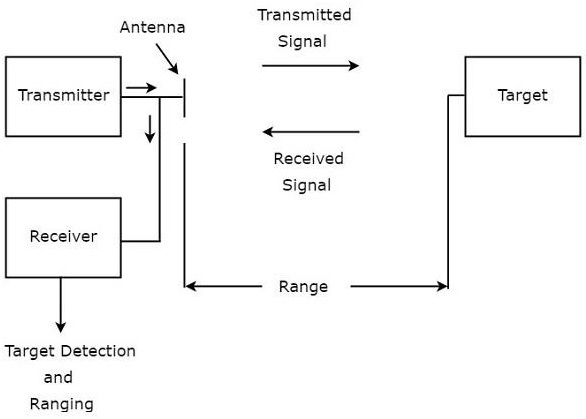
RADAR is an electromagnetic based detection system that works by radiating electromagnetic waves and then studying the echo or the reflected back waves. The full form of RADAR is RA dio D etection A nd R anging. System Block Diagram: Figure 2. Block Diagram of Radar System. Figure 2 represents the system's block diagram. Here, it can be seen how the work flow in this radar system. The sensor is going to sense the obstacle and determine the angle of incident and its distance from the radar. The servo motor is constantly rotating to and fro, hence Doppler Radar Circuit Diagram. Doppler radar integrated module block diagram of the sensor simplified system cw 24ghz will s robotic hb100 fmcw 2 4ghz gain stage help 微. Block Diagram Of The 2 4 Ghz Doppler Radar Integrated On Printed Scientific. Block Diagram Of The 2 4 Ghz Doppler Radar Integrated On Printed Scientific. One Chip Radar Detection Circuit Measuring And Test Diagram Seekic Com. Block Diagram Of The Radar Sensor Circuit Uses A Branch Line Power Scientific. Projects Build A Small Radar System Capable Of Sensing Range Doppler And Synthetic Aperture Imaging Mit Opencourseware.
Pasternack's library RF and microwave block diagram are designed to provide engineers and designers with examples of common RF systems schematics while illustrating the RF products and where they fit into the system's design. ... Radar System. Radar Chip-Set. 13.75 - 14.5 GHz VSAT Radio. 28 - 31.5 GHz VSAT Radio. 71 - 81 GHz E-Band Radio. Radar System Modeling. This example shows how to set up a radar system simulation consisting of a transmitter, a channel with a target, and a receiver. For the Aerospace Defense industry, this is an important multi-discipline problem. RF Blockset™ is used for modeling the RF transmitter and receiver sections. RADAR SYSTEM BLOCK DIAGRAM . Circulator Receiver Protector Synchronous I/ Q Detector ADC and Signal Processor Display Pulse Generator Mixer Mixer Coupler Coupler Oscillator LO PA Radar LNA. ISO 9001 : 2008 Registered Pasternack Enterprises, Inc. P.o. Box 16759, Irvine, CA 92623 Phone: (866) 727-8376 or (949) 261-1920 Fax: (949) 261-7451 operation of the radar. The functional block diagram (fig 2) depicts the eight major systems of the TTR which are: synchronizing system, transmitting system, RF (monopulse duplexer) and antenna system, receiver system, ranging system, antenna position system, presentation system, and RF and IF testing system. A
Block Diagram Of An Fmcw Radar System Download Scientific Diagram
23.2.2020 · Block Diagram of Communication System with Detailed Explanation. Communication By Sasmita February 23, 2020. ... computer communication, radar communication, television broadcasting, radio telemetry, radio aids to navigation, radio aids to aircraft landing etc. ...
Doppler Block Diagram
The sub-level block diagram shown in Figure 3 displays the EW digital radar receiver in more detail than Figure 1. Block 1 mixes an analog RF signal with an analog LO frequency from Block 2 to produce an analog intermediate frequency (IF). The IF signal is sampled by Block 3 to be processed by Block 4. In addition, Block 4 controls the LO ...
Radar Systems Overview
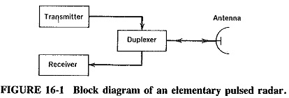
Pulsed Radar System Block Diagram: A very Pulsed Radar System Block Diagram set was shown in Figure 16-1. A more detailed block diagram will now be given, and it will then be possible to compare some of the circuits used with those treated in other contexts and to discuss in detail those circuits peculiar to radar. Block diagram and description:
2
Block Diagram of Radar: The transmitter can be a power amplifier such as klystron, travelling wave tube etc. It can also be a power oscillator such as magnetron. The radar signal is produced at low power by a waveform generator which is then amplified by the power amplifier. The output of the power amplifier is delivered to the antenna by a ...

Block Diagram Of The Monostatic Uwb Microwave Radar System Download Scientific Diagram
The figure below represents the block diagram of a power electronics-based system: As it is clear from the above figure that here we are having a power electronics converter and controller along with some interfacing units. The power converters change one form of electric power into some other form with the use of a power semiconductor device.
Design System Integration And Testing Of Radar Systems Ni
2 System Overview 2.1 Block Diagram Figure 1. SRR System Block Diagram 2.2 Highlighted Products 2.2.1 AWR1642 Single-Chip Radar Solution The AWR1642 is an integrated single-chip, frequency modulated continuous wave (FMCW) sensor capable of operation in the 76 to 81 GHz frequency band. The device is built with TI's low-power, 45-nm
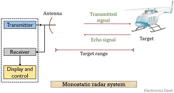
What Is Radar System Definition Basic Principle Block Diagram And Applications Of Radar Electronics Desk
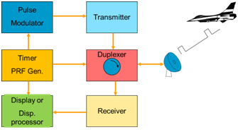
Block Diagram of Pulse Radar. Pulse Radar uses single Antenna for both transmitting and receiving of signals with the help of Duplexer. Following is the block diagram of Pulse Radar −. Let us now see the function of each block of Pulse Radar −. Pulse Modulator − It produces a pulse-modulated signal and it is applied to the Transmitter.
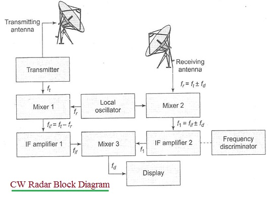
Advantages Of Cw Radar Disadvantages Of Cw Radar
SYSTEM INPUT ATTENUATION FOR RSEC MEASUREMENTS B.1 Hardline Coupling to a Radar Transmitter For hardline-coupled measurements, some attenuation will likely be required between the directional coupler output and the measurement device input (see Figure 1). Referring to this diagram, the minimum decibel amount of attenuation, A, required will be:

Figure 1 From Fpga Signal Processing For Radar Sonar Applications Semantic Scholar
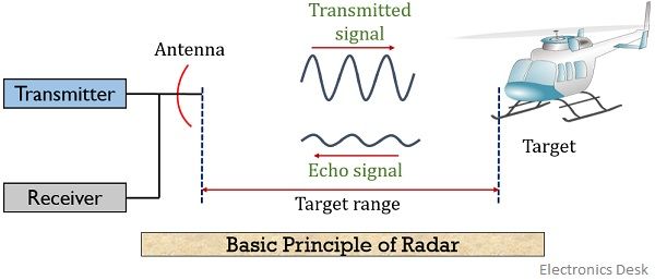
Radar Principle. The electronic principle on which radar operates is very similar to the principle of sound-wave reflection. If you shout in the direction of a sound-reflecting object (like a rocky canyon or cave), you will hear an echo.

Module 1 2 Radar Output Section Kb Gpr Surveys
Radar Design. NOTE: the block diagram and parts lists below specify a MAX414CPD+ quad op-amp, which is no longer manufactured. Any quad op-amp will work, such as a TI LM324. Radar System design slides: block diagram, schematics, bill of material, and fabrication instructions (PDF - 4.6MB) Block diagram (high resolution image)
1
May 24, 2021 · Basic Radar Block Diagram. A basic radar block diagram is shown in Fig. 1. The pulse repetition frequency is controlled by the timer (also called trigger generator or synchronizer) in the modulator block. The pulse-forming circuits in the modulator are triggered by the timer and generate high-voltage pulses of rectangular shape and short duration.

Nxp S Radar Block Diagram Electronic Products
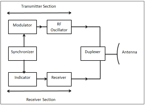
Block Diagram of Radar System. The typical block diagram of radar system is shown in Figure. The essential elements of a radar system are: The timer device is used for coordinating the action of the transmitter, receiver, and indicator, to ensure synchronized operation. ...
1
Content: Radar System. History; Principle; Block Diagram; Applications; History. Radar was invented for military purpose before world war II in order to secretly detect the presence of unknown objects. Initially, the transmitting tubes were not that much powerful thus worked at a very low frequency of about 60 MHz.. But further development in the field and use of magnetrons has extended the ...
Military
The below figure represents a typical system for traffic radar. For multi-piece radars the antenna is usually separate from the rest of the electronics. Figure D-1-- Radar Block Diagram. Antenna GAIN Antenna gain (G) can be expressed in terms of wavelength (Lambda) and effective antenna area (A e). Effective antenna area is physical area (A ...
2
28.7.2019 · Fig. (i) shows the block diagram of a general communication system, in which the different functional elements are represented by blocks. Fig. (i) The necessary components of a communication system are an information source, input transducer, transmitter, communication channel, …
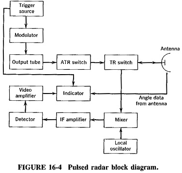
Pulsed Radar System Block Diagram Types Of Modulators
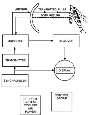
The basic parts of a radar system are illustrated in the simple block diagram of fig.1. Radar equipment consists of a transmitter, an antenna, a receiver, and a signal processor.

Radar Principle Radartutorial
Figure 1: Universal Block Diagram of Pulse Radar This block diagram may be used for your own lessons but there are no block labels in the animation and there is no background image (landscape). These block labels can be placed in an own layer over the animation in e.g. MS-PowerPoint with text boxes in your own language version.
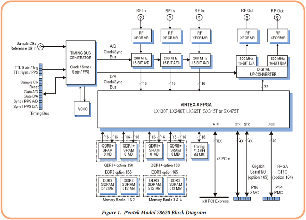
Pentek Model 78620 With Gt Asgm18a And Gt Asam18a
S32R29x Applications Block Diagram Close Blind Spot Detection and Lane Change Assist Close Cross Traffic Junction Assist Close 360 Degree ... Complete Radar System Solution Previous Next. × S32R294 Block Diagram. × S32R29x ...
Basic Radar System Block Diagram Fundamentals Frequencies And Powers
The radar antenna illuminate the target with a microwave signal, which is then reflected and picked up by a receiving device and Radar signals can be displayed on the traditional plan position indicator (PPI) other more advanced radar display systems Fig.2: Block diagram of a primary radar 8.
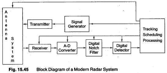
Block Diagram Of A Modern Radar Systems Analysis
Rendezvous Radar System Block Diagram. TRANSPONDER ANTENNA. The transponder utilizes two antenna systems, (Figure Below) a dipole antenna array and two dual spiral antennas. The selected antenna system is connected to the transponder by an antenna select switch. The dipole antenna array is located on an extendable boom which is retracted until ...
C Band Portable Multi Mode Radar Z Peng
Basic radar block diagram. Synchronizer. The heart of the radar system is the ,synchronizer. It generates all the necessary timing pulses (triggers) that start the transmitter, indicator sweep circuits, and ranging circuits. The synchronizer may be classified as either self-synchronized or externally synchronized. In a self-synchronized system ...

General Block Diagram Of The Radar System Download Scientific Diagram
Block Diagram Showing CW RADAR Radar Range Equation. There are different kinds of versions available for the radar range equations. Here, the following equation is one of the fundamental types for an only antenna system. When the object is assumed to be in the middle of the antenna signal, then the highest radar detection range can be written as

Block Diagram Of The Radar System S Configuration Download Scientific Diagram
Wideband Radar System Testing Electronics Maker
What Is Radar System Definition Basic Principle Block Diagram And Applications Of Radar Electronics Desk

Sensors Free Full Text Portable Microwave Radar Systems For Short Range Localization And Life Tracking A Review Html

Working Of A Pulse Radar And Its Applications
Basic Radar Systems

A Technical View Into Modern Mil Aero Radar Systems Edn
What Is Radar System Definition Basic Principle Block Diagram And Applications Of Radar Electronics Desk

Microasar Eoportal Directory Airborne Sensors
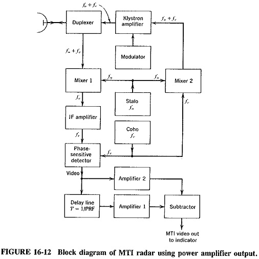
Moving Target Indicator Radar Block Diagram Operation Of Mti Radar
What Is Radar And How Many Types Of Radar Is Used Nowadays Quora
Keysight Technologies Uk New Facelift For Radar But The Physics Stay The Same

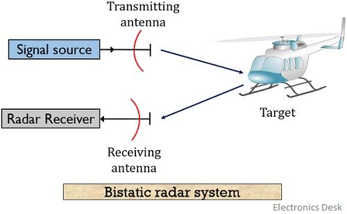
Engineering Made Easy Radar Block Diagram And Working Bistatic Radar And Monostatic Radar Types Of Radar

Radar Principles Systems Two Basic Radar Types U

Advanced Radio And Radar Ppt Video Online Download
Radar Electronic Tutorial Mepits Mepits
Draw The Block Diagram Of A Radar System And Explain The Function Of Each Block Sarthaks Econnect Largest Online Education Community
Basic Block Diagram Of Radar Communication 1 Download Scientific Diagram
Radar Components


Comments
Post a Comment