38 ph diagram of refrigeration cycle
P-h diagram of vapor compression refrigeration cycle Generally, the vapor compression refrigeration system consists of a condenser, an expansion valve, an evaporator, and a compressor. The vapor ... Learn how to draw a cycle for ideal conditions on a PH chart.Please provide feedback on this module by selecting "Like" or "Dislike". Your feedback and comme...
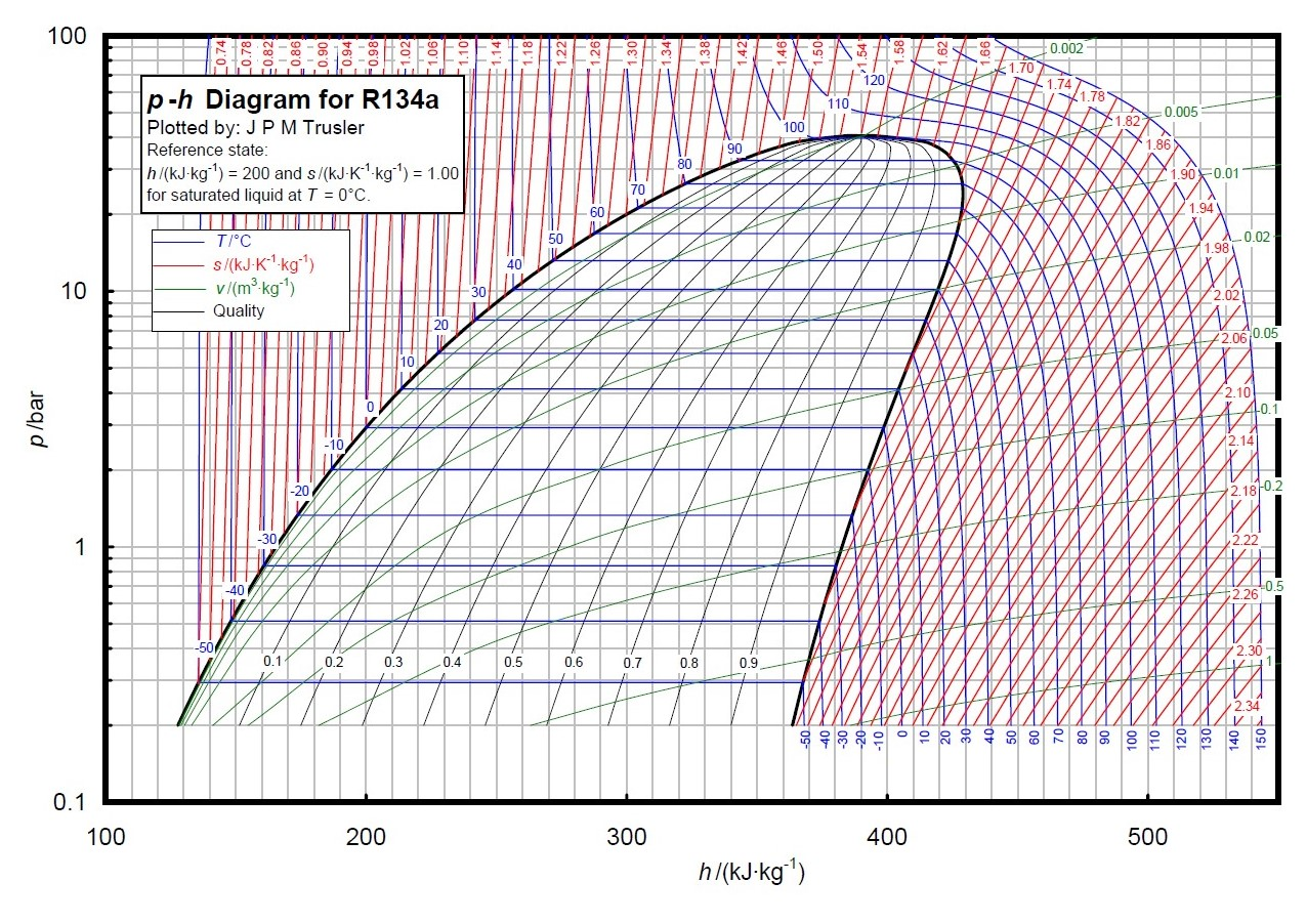
It is recommended that the engineer get a copy of the P-H diagram for R-134a and the other common refrigerants. These diagrams can be found in the ASHRAE Fundamentals book. A sample R-134a diagram is shown below, with a sample refrigeration cycle, identifying (Step 1) Evaporator, (Step 2) Compressor, (Step 3) Condenser and (Step 4) Expansion ...
Ph diagram of refrigeration cycle
The p h diagram is another convenient diagram often used to illustrate the refrigeration cycle. A p h diagram for r22 in si unit is used. These diagrams can be found in the ashrae fundamentals book. The first step in plotting a refrigeration cycle on a ph diagram is to establish the condensing and evaporating lines. Figure 1: Vapor-Compression Refrigeration Cycle T-s diagram Below is a possible CyclePad design of a refrigeration cycle. The layout shown below is a clickable image. To jump to the part of this page that details the assumptions of a particular device or statepoint, just click on it. Principles of Refrigeration MAE 554 Professor H. Ezzat Khalifa Syracuse University P-h Chart for R134a (SI Units) ... P-h Diagram for Real Vapor Compression Cycle ... P-h Diagram for 2-Stage VCC with Subcooler. 11 0.6 0.8 1.0 1.2 1.4 1.6 1.8 2.0 2.2 2.4-40 -30 -20 -10 0 10203040 50
Ph diagram of refrigeration cycle. Fig. 11. T-S diagram for Wet Vapour Compression Cycle Fig. 12. P-h diagram for Wet Vapour Compression Cycle In this cycle, enthalpy at state 2 is found with the help of dryness fraction at this point (2). The dryness fraction at points 1 and 2 may be obtained by equating entropies at state 1 and 2. C.O.P = = Refrigeration cycle in the log p-h diagram. Green = compressor. Red = condenser. Yellow = expansion valve. Blue = evaporator. 1 - 2 polytropic compression to the condensing pressure (for comparison 1 - 2' isentropic compression) 2 - 2'' isobaric cooling, deheating of the superheated vapour. 2'' - 3' isobaric condensation. The vapor-compression cycle is used by many refrigeration, air conditioning and other cooling applications and also within heat pump for heating applications. There are two heat exchangers, one being the condenser which is hotter and releases heat and the other being the evaporator which is colder and accepts heat. For applications which need to operate in both heating and cooling mode a ... 5.The compression refrigeration cycle on the h-log p diagram 6. Heat pump technology 7. Ice banks 4. 7.6 Ice bank control 84 7.6.1 Control of the glycol-water mixture's temperature 84 7.6.2 Control of the diverting valve according to operating mode85 7.6.3 Ice bank charging control 85
The refrigeration cycles can also be represented in a P-H diagram. Figure 5: P-H diagram representation of a dry refrigeration cycle Refrigerant fluid choice: We now turn our attention to the fluids. Usually, one tends to pick pL as low as possible, but not below atmospheric pressure. Thus, the refrigerant chosen needs to have a normal boiling ... Defined by a cycle of transfers into and out of a system, a cyclic process is described by the quantities transferred in the several stages of the cycle. The descriptions of the staged states of the system may be of little or even no interest. A cycle is a sequence of a small number of thermodynamic processes that indefinitely often, repeatedly returns the system to its original … The P-h diagram is another convenient diagram often used to illustrate the refrigeration cycle. The ordinary household refrigerator is a good example of the application of this cycle. Results of First and Second Law Analysis for Steady-Flow Component Process First Law Result Compressor s = const. Wmhh () in =−21 07.10.2020 · 🚨 Our Ph.D. Program within @mayoclinicgradschool is currently accepting applications! As a student, you'll join a national destination for research training! Here are a few need-to-know highlights: ⭐ Eight specialization tracks, including the NEW Regenerative Sciences (REGS) Ph.D. track. This track is one of the nation's first doctoral research training …
PH P X IC E MA CHI NE MO DE L I -I ndi go Mo del IB -I ce Be ve r age CU BE SI ZE R Y -R egul ar D -D ic e-H al f-Di ce No t Us ed On IB M ode ls Ic e Ma ch i ne Se ri es CO NDE NS ER ai TY PE A -S el f-Co nt ned Ai r-Co ol ed W -S el f-Co nt ai n ed Wa te r-C ool ed N -R em ot e Ai r-Co ol ed C -C VD Ai r-Co ol ed DC -I B Di ce M ode l YC B Ha ... The refrigeration cycle in the log p-h diagram The refrigeration cycle in the log p-h diagram The real refrigeration cycle consists of the following changes of state: 1 - 2 polytropic compression on the condensation pressure (for comparison 1 - 2' isentropic compression) 2 - 2'' isobaric cooling, deheating of the superheated steam Most refrigeration cycles are typically represented by a pressure-enthalpy (P-h) diagram, which shows the phase changes of the refrigeration cycle and provides a graphical means of study. Horizontal lines on the P-h Chart are lines of constant pressure and vertical lines are lines of constant enthalpy or heat energy. The Refrigeration Cycle - Complete: Fig 5. In this final diagram of the refrigeration cycle we have introduced 3 new terms: Superheated, Saturated & subcooled. SUPERHEAT - Is an amount of heat added to refrigerant vapour beyond its boiling point. This ensures the refrigerant is in a gas state with no liquid present.
Design Of Vapor Compression Refrigeration Cycles
Welcome to Engineering Solutionswith Akshay In this video we will come across the schematic representation and working of Vapour Compression Refrigeration Cy...
Solved A R134a Mechanical Refrigerator Operating With The Chegg Com
The SEPIC is a type of DC/DC converter that allows the electrical potential (voltage) at its output to be greater than, less than, or equal to that at its input. The output of the SEPIC is controlled by the duty cycle of the control transistor. The circuit diagram is shown in Fig. 7.12.
What Is The T S Diagram For The Carnot Refrigeration Cycle Quora
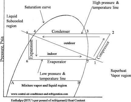
If you are interested in learning how a refrigeration system works, it is helpful to understand from the Ph (Pressure Enthalpy) chart perspective. It makes our life much easier. This is how the refrigeration cycle diagram looks: Yeah, it seems complicated at first, but it will be easier to understand once I have explained the refrigeration ...

Efficiency Measuring Refrigeration
Understanding the basic refrigeration cycle diagram also helps us to find subcooled, superheat and to troubleshoot refrigeration processes much easier. As we can see in the Ph diagram below. Saturation curve this curve represents what state (vapor or liquid) and region (sub-cooled, latent heat, and superheat) the refrigerant is in.

Refrigeration Cycle Diagram Explained Refrigeration Hvac R And Solar Energy Engineering
The first step in plotting a refrigeration cycle on a PH diagram is to establish the condensing and evaporating lines. Take the system operating pressures and convert them to absolute pressure by adding 15 These pressures will be used to establish the evaporator and condenser lines. (Pg 291)

Refrigeration Sciencedirect
Download scientific diagram | Pressure-Enthalpy (P-h) diagram of: (a) an ideal refrigeration cycle, (b) a typical refrigeration cycle [5]. from publication: The Effect of Refrigerant Charge and ...
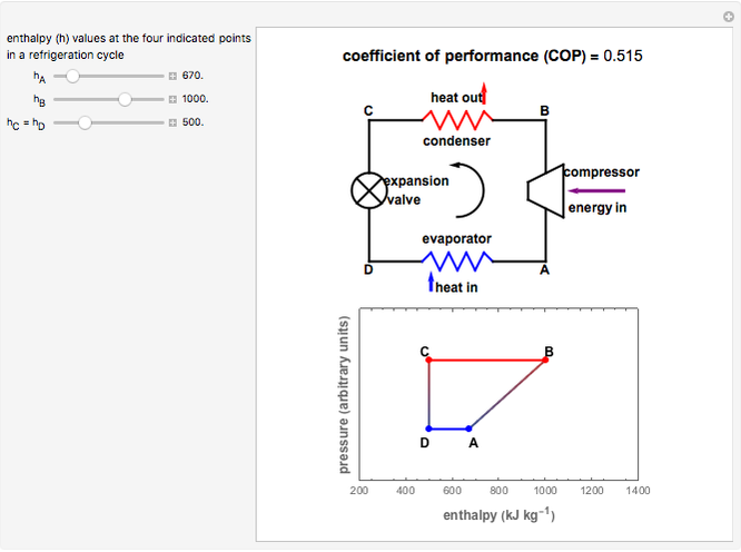
Refrigeration Cycle Coefficient Of Performance Wolfram Demonstrations Project
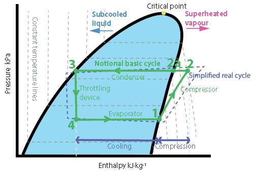
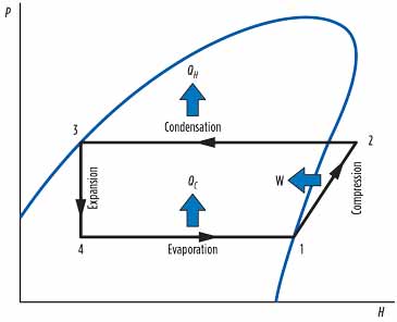
The following example is a simplified p-h diagram on which a refrigeration cycle is drawn. Point 1 to 4 show the following. Point 1 to 2: Refrigerant change in a compressor. Point 2 to 3: Refrigerant change in a condenser. Point 3 to 4: Refrigerant change through an expansion valve. Point 4 to 1: Refrigerant change in an evaporator.

6 Vapor Compression Cycle
R134a Refrigerant Ph Chart. Enthalpy diagram of thermodynamic cycle p h diagram showing the refrigeration p h diagram thermodynamics hvac and thermodynamic scope for two phase fluid lab 3 ph diagram 1 et 102 p h. Pressure Enthalpy Chart Of Rankine Cycle With R134a For First Se Scientific Diagram.

P H Diagram Of An Ideal Vapor Compression Refrigeration Cycle
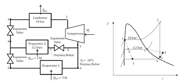
Two-Stage Refrigeration System Temperature of Refrigerator(E04) = Dew point temperature of propane at 5.2239 bar = -69.74 oC First Stage Discharge Pressure(K04) = Suction Pressure * Ratio per stage = 1.665 * 3.1375 = 5.2239 bar Ratio per stage Condenser Heat Duty of C1 Refrigeration Cycle(E09) = 56.2055*106Kcal/hr 19/33
Solved Draw The Logarithm P H Diagram Of The Vapor Chegg Com
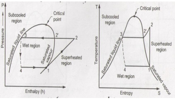
P-H Diagram for Ideal Conditions e . H 1 = h f based on temperature at 'd' (exit of condenser) H 2 = h g based on temperature at 'a' (exit of evaporator) Note 1: If there is super -heating in the evaporator, H 2 can not be obtained from P-H table Note 2: If there is sub- cooling in the condenser, H 1 can not be obtained from P-H table
1
Figure 2.9 The real refrigerant cycle in the log P/h diagram. The overheating is the difference between the temperatures at points 1.1 and 1.2. The sub-cooling is the difference between the temperatures at points 3.1 and 3.2. Figure 2.10 Log P/h diagram with temperature levels shown. Figure 2.11 The energy flow in a refrigerant system.
Jsrae Japanese Society For Refrigerating And Airconditioning Engineers
Figure 4 is a pressure-enthalpy diagram of a typical refrigeration cycle in a system with one pound of HFC-134a. It uses (for this example) evaporating and condensing temperatures of 0°F and 120°F. Points on the diagram are labeled to correspond to locations of equipment in the system. Each step of the cycle can be approached separately.
What Is The Difference Between Refrigeration Effect And Refrigeration Capacity Are They Same Coz Units Are Same Quora
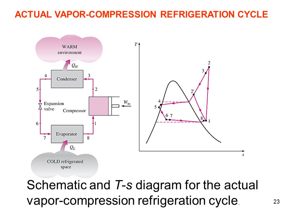
M. Bahrami ENSC 461 (S 11) Refrigeration Cycle 3 Fig. 5-3: T-s and P-h diagrams for an ideal vapor-compression refrigeration cycle. 1-2: A reversible, adiabatic (isentropic) compression of the refrigerant. The saturated vapor at state 1 is superheated to state 2. wc =h2 − h1

The Refrigeration Cycle
Refrigeration handbook 1. Basic heat transfer 2. Compression cycle 2.1 The pressure-enthalpy diagram; 2.2 Basic components; 2.3 The basic cycle in a log Ph diagram; 2.4 The complex cycle in a log Ph diagram; 2.5 Other components; 3. Compressors 4. Expansion valves 5. Refrigerants 6. Evaporators 7. Condensers 8.
Module 146 Ensuring Safe Environmentally Sensitive Refrigerants For Building Services Applications Cibse Journal
The P-H Diagram of the refrigeration cycle with all the operating conditions are as the following: Figure 1-9 P-H Diagram for the Refrigeration System Figure 1-10 Refrigerant Flow Diagram for the Refrigeration System . Practice-2: The CT, ET and TR are the same as Practice-1
Solved 2 Question 2 40 Points Refrigeration Cycle Refer Chegg Com
Principles of Refrigeration MAE 554 Professor H. Ezzat Khalifa Syracuse University P-h Chart for R134a (SI Units) ... P-h Diagram for Real Vapor Compression Cycle ... P-h Diagram for 2-Stage VCC with Subcooler. 11 0.6 0.8 1.0 1.2 1.4 1.6 1.8 2.0 2.2 2.4-40 -30 -20 -10 0 10203040 50
Projects Ncsu Edu
Figure 1: Vapor-Compression Refrigeration Cycle T-s diagram Below is a possible CyclePad design of a refrigeration cycle. The layout shown below is a clickable image. To jump to the part of this page that details the assumptions of a particular device or statepoint, just click on it.
Refrigeration And Heat Pump Systems Vaporcompression Refrigeration Cycle
The p h diagram is another convenient diagram often used to illustrate the refrigeration cycle. A p h diagram for r22 in si unit is used. These diagrams can be found in the ashrae fundamentals book. The first step in plotting a refrigeration cycle on a ph diagram is to establish the condensing and evaporating lines.

Refrigeration Cycle Diagram Explained Refrigeration Hvac R And Solar Energy Engineering
Refrigeration Basics Definitions Part 2

Vapour Compression Refrigeration Cycle It S Schematic And T S P H Diagram Youtube

Vapor Compression Refrigeration Cycle Interactive Simulation Youtube

Category Using Pressure Enthalpy Diagrams Fundamental Refrigeration
Ou Edu

Fault Diagnosis Of A Vapor Compression Refrigeration System With Hermetic Reciprocating Compressor Based On P H Diagram Sciencedirect

Experimental Comparison Between R409a And R437a Performance In A Heat Pump Unit
Smart Coolant For Ngl Processing In Very Hot Regions
Explain Vapour Compression Refrigeration Cycle On T S And P H Charts Topicwise Paper Solutions For Msbte

Wazipoint Engineering Science Technology Refrigeration Cycle Of Centrifugal Chiller

Two Phase Fluid Refrigeration Matlab Simulink
Resources Saylor Org

Pressure Enthalpy As A Service Tool Achr News
5 Vapour Compression Cycle On Ph And T S Diagrams Lessons Blendspace
Basic Refrigeration Cycle

The Refrigeration Cycle
Design Of Vapor Compression Refrigeration Cycles

Refrigeration Cycle Diagram Refrigeration And Air Conditioning Electrical Symbols Mechanical Engineering
Jsrae Japanese Society For Refrigerating And Airconditioning Engineers


Comments
Post a Comment