39 emergency ballast wiring diagram
November 25, 2016 - Trying to wire a ballast up with fewer terminals than the existing one? It can look confusing but it really isn’t too bad when you know how… use our downloadable cheat sheet! Manufacturers of fluorescent high frequency ballasts are constantly looking for new ways making their ballasts more ... The diagrams are categorized primarily according to the number of lamps in the fixture, then followed by the ballast type. Sometimes a specific lamp type is.
Emergency Battery Ballast Wiring Diagram. By grandcaret | November 12, 2021. 0 Comment. Bal60lummanu0046e 06 02 20 a guide to emergency ballast for led and fluorescent lamps sanforce lbd 00418j 4 70w 1000v dimmable light febnet02 rf modem user manual b50 febnet 75000022 pmd the bodine je woo driver 15 watts max 25 48v output 120 277v input jen ...

Emergency ballast wiring diagram
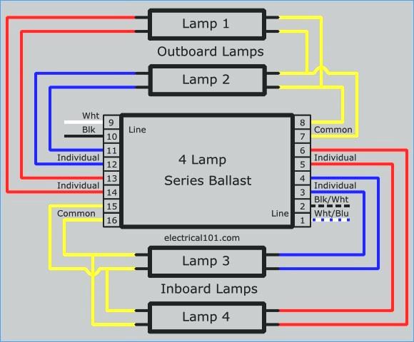
Ballast EMERGENCY BALLAST RELAY HOW TO USE THE EMERGENCY BALLAST WIRING GUIDE This Document has been customized to contain a wide library of individual dia-grams for various installation applications. If a diagram cannot be found within this selection, consult Customer Service. The diagrams are categorized primarily according to the number of ... Download the latest Bodine product specification sheets, instructions, catalogs and other materials. 4 lamp 2 ballast wiring diagram.Each lampholder has four separate connections. Ge 120 To 277-Volt Electronic Ballast For 8 Ft. 4 bulb ballast wiring diagram 4 lamp t12 ballast 4 lamp emergency ballast wiring diagram wiring diagram manual barbie games co File Type.
Emergency ballast wiring diagram. Refer to the wiring diagrams on the back page for the appropriate wiring of lamp(s) and ballast. Install in accordance with the National Electrical Code and ... CONSULT THE FACTORY FOR OTHER WIRING DIAGRAMS. EMERGENCY BALLAST AND AC BALLAST MUST BE FED FROM THE SAME BRANCH CIRCUIT. 2.A) FLEX Conduit Wiring Diagram:. AC power to the emergency ballast. 9. The battery needs to be charged for one hour in order to have short-term testing on the emergency function. Before having a long-term emergency function testing, the battery in the emergency ballast has to be charged for 24 hours. DIAGRAM 2 Test Switch Charging Indicator Light Emergency Ballast Charging ... Iota Emergency Ballast Wiring Diagram Download Peterbilt Concert Class Radio Wiring Diagram. The best marginal is always to use a verified and accurate peterbilt stereo wiring diagram that's provided from a trusted source. A good, conventional company that has a long track photograph album of providing the most up-to-date wiring diagrams easy ...
Wiring diagram for the current signPro line of Phillips Advance fluorescent ballasts Tridonic is a world-leading supplier of lighting technology, supporting its customers with intelligent hardware and software and offering the highest level of quality, reliability and energy savings. Fluorescent Emergency Ballast Wiring Diagram - Wiring Diagram - Ballast Wiring Diagram Furthermore, Wiring Diagram gives you the time body by which the assignments are for being accomplished. You may be able to understand exactly if the projects needs to be finished, that makes it much simpler for you to effectively handle your time and effort. Fluorescent Ballast Labels. The label on the ballast shows two important labels. Lamp compatibility table (type of lamps that can be used with this ballast) Ballast wiring diagram (shows how the ballast is wired to the lamps) Fluorescent Tube Diameters. Fluorescent tubes have two common shapes, straight and u-shaped. The most common types are ...
Atlas Lighting provides a wide selection of quality. energy-efficient and fast-selling LED, Fluorescent and HID lighting products—all manufactured and quality tested in the USA. Today’s product offering is focused on high quality and fast selling LED wall lights, flood lights, area lights, ... Fluorescent Emergency Ballast Wiring Diagram. vivian.flatley October 5, 2021 Templates No Comments. 21 posts related to Fluorescent Emergency Ballast Wiring Diagram. Fbp 1 40x Fluorescent Emergency Ballast Wiring Diagram. Fbp 2 40h Fluorescent Emergency Ballast Wiring Diagram. DO NOT MATE CONNECTOR UNTIL. INSTALLATION IS COMPLETE AND. AC POWER IS SUPPLIED. LAMP SELECTOR LEADS—REFER. TO INSTALLATION INSTRUCTIONS,. Emergency ballasts have many wiring diagrams depending on the following. To prevent high voltage from being present on the DEB-1W output leads red and yellow do not join the battery connector until installation is complete and AC power is supplied to the DEB-1W. May be used with other ballasts. INSTALLING THE LED COMBO TEST SWITCHLCTS 4.
T8 Emergency Ballast Wiring Diagram - Complete Wiring Schemas
Nov 04, 2018 · Ballast compatibility will vary by manufacturer and must be checked before installation. Additionally, a UL Type A tube sacrifices efficiency due to the additional power loss from the existing ballast and is limited in dimming and controllability. Type B – Simplest Total System. Ballast Bypass LED Tube – Wired to Mains
Iota I-24 Emergency Ballast Wiring Diagram
4. Wire the luminaire following the wiring diagram on the ballast, or inside the box. Use UL listed wire connectors suitable for the size, type, and number of conductors. No loose strands or wires should be present. Secure wire connectors with UL listed electrical tape and wire nuts. 5. Install lamps (not included). Do not exceed recommended ...

Iota Emergency Ballast Wiring Diagram | Free Wiring Diagram
Electrical101 does not recommend ... replacing both the standard and emergency ballasts and starting from scratch. A diagram will come with the new emergency ballast to help you wire it properly....

Emergency Light Ballast Wiring Diagram - Emergency ...
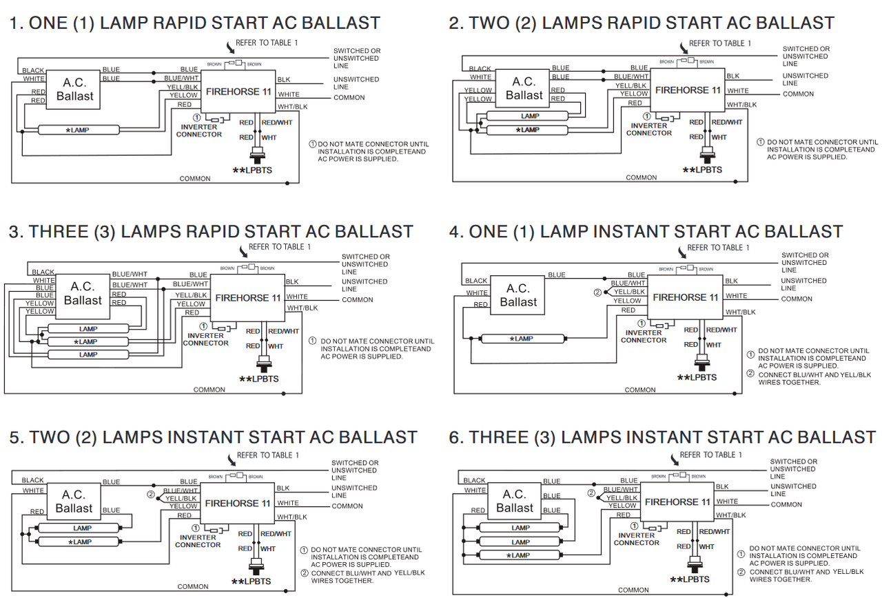
Rapid Start ballast lampholder wiring diagrams are shown with different numbers and combinations of lamps.

Iota I-80 Emergency Ballast Wiring Diagram
Wiring Diagram Finder. Find wiring diagrams for your WorkHorse, WHAM, or LongHorse ballasts. Select your lamp type from the list below. Select the lamp quantity and wattage. Select the ballast family. Select your ballast. To download the diagram, right click the image when it appears and choose “Save as…”. Twin.

Fbp 1 40x Fluorescent Emergency Ballast Wiring Diagram ...
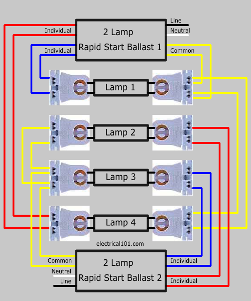
Jul 22, 2017 - 4 lamp rapid start ballast wiring diagrams are shown. These diagrams are shown on the ballast label.
Ge Ultramax Ballast Wiring Diagram
Number of the ac ballast that the emergency unit is being wired to, you may use the "find" tool in the toolbar (denoted by the binocular icon) to search the diagrams for that particular model. The power is on one end (single end); If one lamp fails, the others can keep operating as the circuit between them and the ballast remains unbroken.
Iota Emergency Ballast Wiring Diagram Download | Wiring ...
August 17, 2021 - The basic function of an electronic ballast (or electrical ballast) is to control the starting voltage and the operating currents of lighting devices. To find out which of the basic component is not used in electronic ballast ...

347V Wiring Diagram - Ultrasave PR232347-PP-HE - 1- Lamp ...
wiring diagram for applicable lamp and ballast configuration. CAUTION: This emergency ballast is designed for factory or field installation in either the ...
Iota I-80 Emergency Ballast Wiring Diagram
Wiring Diagram T12 To T8 Ballast Wiring Diagram by Vallery Masson updated on October 11, 2021 It is intended to aid each of the common person in developing a proper program. 2 lamp rapid start to. This Led Emergency Ballast Installs Within The T5 T8 Lighting Fixture And Provides Emergency Lighting In The Event Of A Power Loss

Bodine B100 Emergency Ballast Wiring Diagram | Free Wiring ...
Emergency ballast wiring diagram. Literally a circuit is the path that enables electrical energy to circulation. A wiring diagram is a streamlined standard photographic representation of an electrical circuit. It shows the components of the circuit as simplified forms and the power and signal links in between the devices.
T10.T12 Rapid Start Ballasts_AM105_3-4 Lamps - Ballast ...
Adapting to ever-changing technologies within commercial lighting, H.E. Williams proudly offers a complete lighting solution of indoor and outdoor products.

Emergency Fluorescent Light Wiring Diagram | Fuse Box And ...
Lithonia Lighting Psq500 Wiring Diagram. Psq500 ps600 ps1400 installation wire diagrams manualzz psq500dw power sentry psq500qd mvolt emergency ballast lithonia lighting ps300qd instructions ps600dw field install psl600 ps1400qd m8 nickel cadmium battery pack guide fluorescent backup energy avenue adding a second light to existing 3 way circuit ...

Emergency Light Ballast Wiring Diagram - 2 Hours Dutation ...
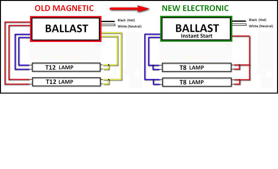
How to Switch From a Magnetic Ballast to an Electronic Ballast. Older fluorescent light fixtures utilized a magnetic ballast to control the flow of electricity through the light bulbs. Magnetic fixtures required a separate starter to kick-start the flow of electrons through the tubes.

Closeup of skeleton pelvic model
• Emergency mode: If the emergency PowPak loses power**, it will automatically go into emergency mode (full output, relay closed) for 90 minutes, when emergency power is restored to the PowPak. The RMJS-8T-DV-B-EM will not respond to all local button presses, Pico wireless controls, occupancy and daylight sensors for 90 minutes.
![[DIAGRAM] Electronic Ballast Schematic Diagram FULL ...](https://wholefoodsonabudget.com/wp-content/uploads/2018/08/electronic-ballast-wiring-diagram-electronic-ballast-wiring-diagram-fresh-ballast-wiring-diagram-splendid-appearance-robertson-isl-10c.jpg)
[DIAGRAM] Electronic Ballast Schematic Diagram FULL ...
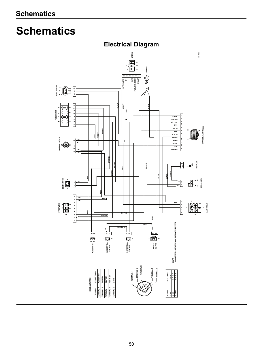
Jan 01, 2005 · That portion of the system which is used to indicate temperature, pressure, control positions, etc. of the air systems. Includes items such as transmitters, indicators, wiring, etc. 76 : ENGINE CONTROLS: Those controls which govern operation of the engine. Includes units and components which are interconnected for emergency shutdown.

Iota I 24 Emergency Ballast Wiring Diagram | Free Wiring ...
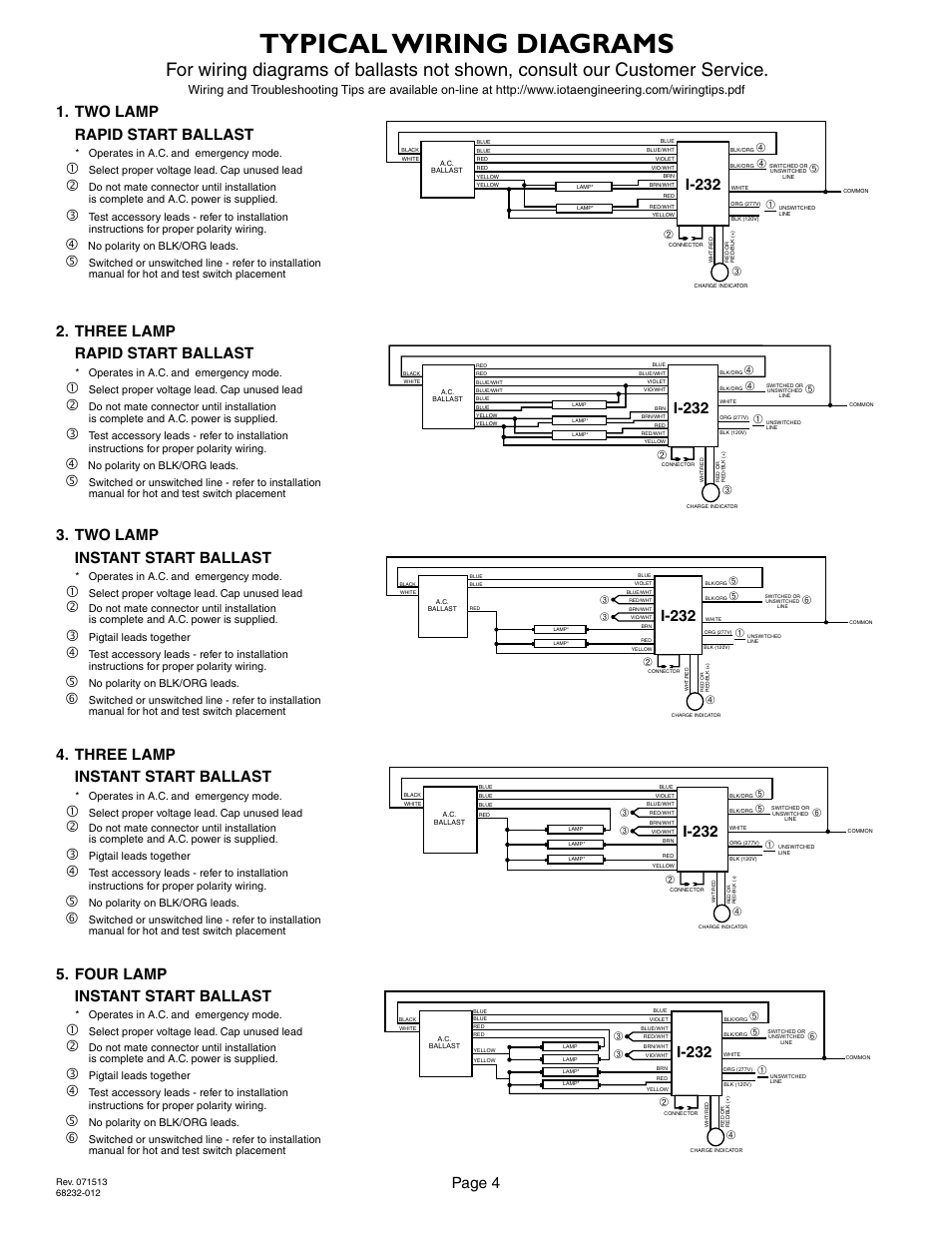
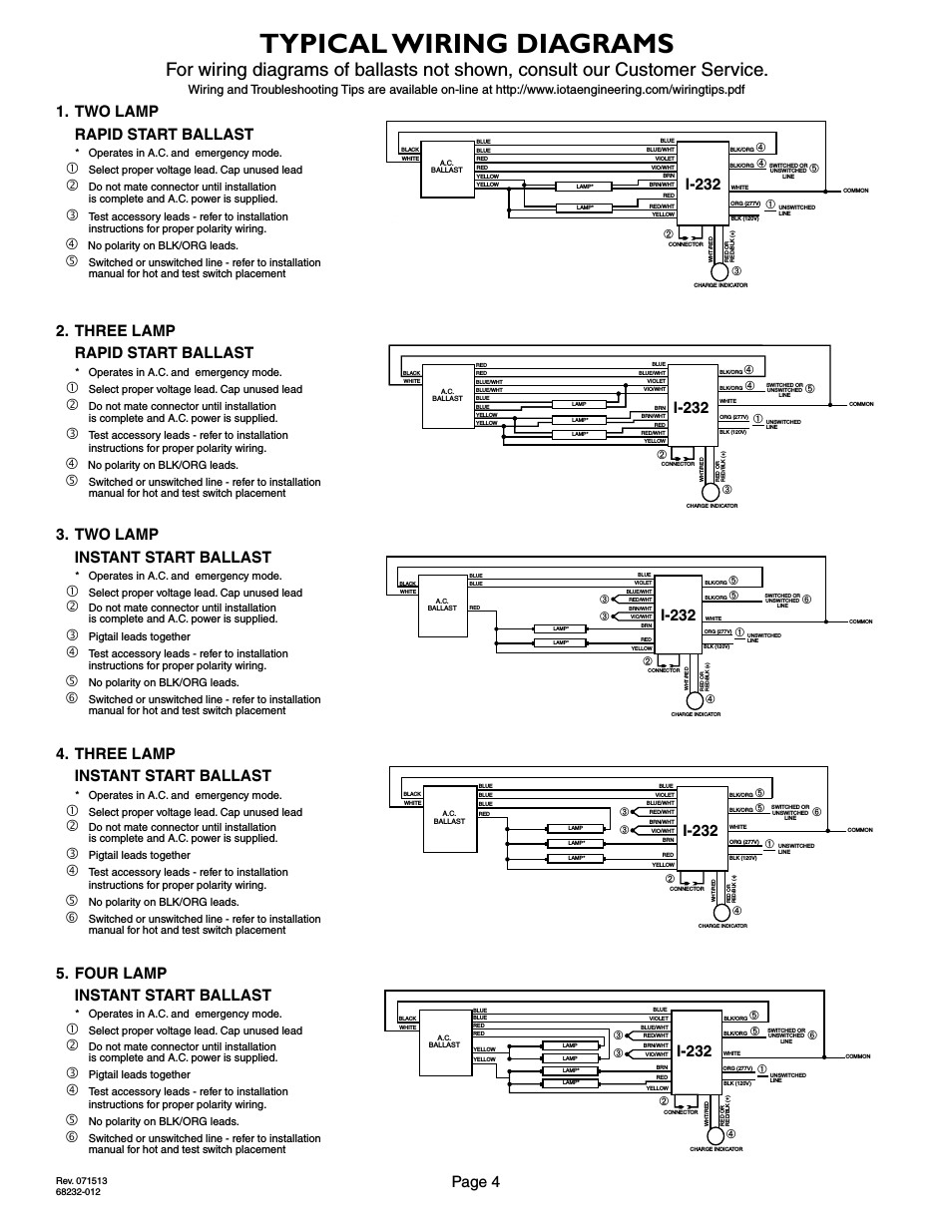
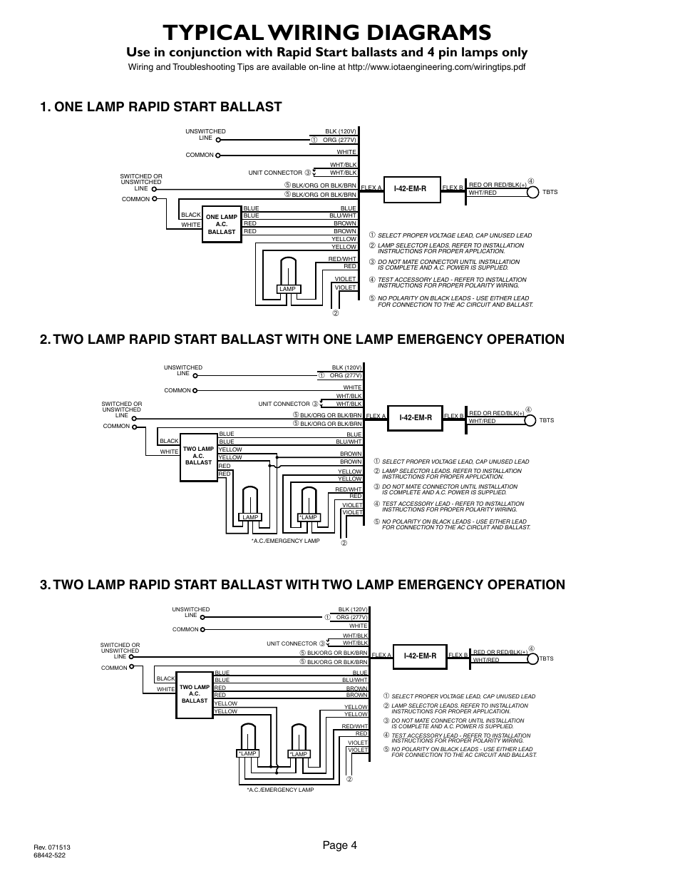
2LRSB_232_D. TWO LAMP RAPID START BALLAST. OPERATES IN A.C. AND. EMERGENCY MODE. SELECT PROPER VOLTAGE. LEAD. CAP UNUSED LEADS. DO NOT MATE CONNECTOR UNTIL.

T8 Emergency Ballast Wiring Diagram - Complete Wiring Schemas
The Complete Guide to Electrical Wiring. Angky Tri Aditya. Download Download PDF. Full PDF Package Download Full PDF Package. This Paper. A short summary of this paper.
Bodine Emergency Ballast Wiring Diagram
Select the appropriate wi ing diagram to connect the emergency ballast to the AC ballast and lamp Make sure ... 1/2" hole and install the switch as shown (see Illustration 1 2) Refer to the wiring diagrams section and wire the test switch so it removes AC power from the unswitched hot line to the emergency ballast.

Philips Advance Ballast Wiring Diagram Download
Hbl5266c Wiring Device Kellems. Emergency lighting control relay ridgeline series installation ul924sr 1 2 install guide ufo 6w 4w bal60lummanu0046e 06 02 20 batteryguy ballast pld dual cf1 instructions led battery pack hubbell c i compass cels quick fluorescent controls product exit light cx relays brochure datasheet by thomas pharos dmx bypass shunt e96 replacement hbl5266c wiring device ...
4 Lamp T8 Ballast Wiring Diagram - Cadician's Blog
Ballast EMERGENCY BALLAST RELAY HOW TO USE THE EMERGENCY BALLAST WIRING GUIDE This Document has been customized to contain a wide library of individual dia-grams for various installation applications. If a diagram cannot be found within this selection, consult Customer Service. The diagrams are categorized primarily according to the number of ...

Bodine Emergency Ballast Wiring Diagram | Wiring Diagram
Wiring Diagram Of Twin Tube Light Fluorescent Lamp Tube Light Diagram . T8 Ballast Wiring Diagram In 2021 Led Fluorescent Tube Led Tubes Led Tube Light . Wiring Diagram For A Single Tube Light Circuit Tube Light Circuit Diagram Circuit . Pin On Duraspark Wiring . Hid Ballast Wiring Diagrams For Metal Halide And High Pressure Sodium Ballasts ...

I32 Emergency Ballast Wiring Diagram
How to wire electronic ballast

INSTAGRAM - @LGNWVR LGNWVR.COM
Wiring diagrams and descriptions to help you understand fluorescent ballasts, including series and parallel ballasts.
2 Lamp Ballast Wiring Diagram
Don't just assume that wires at ... the old ballast. In this case they do not. Notice also that the "green" wire in the original transformer diagram is NOT a ground wire. ... Black - line hot - wire is at the right end of the transformer where a pair of blue wires emerge...
Iota I-24 Emergency Ballast Wiring Diagram
Includes Lithonia Lighting® exit ... IOTA® emergency drivers and inverter systems, and IOTA® and nLight® ALCR solutions. ... How engineering diligence and careful handling helps improve reliability of IOTA ILBLP drivers. ... This guide from IOTA explains the effects of resistance on multiple batteries wired in parallel, ...
Iota I32 Emergency Ballast Wiring Diagram
Ballast EMERGENCY BALLAST RELAY HOW TO USE THE EMERGENCY BALLAST WIRING GUIDE This Document has been customized to contain a wide library of individual dia-grams for various installation applications. If a diagram cannot be found within this selection, consult Customer Service. The diagrams are categorized primarily according to the number of ...

T8 Emergency Ballast Wiring Diagram - Complete Wiring Schemas
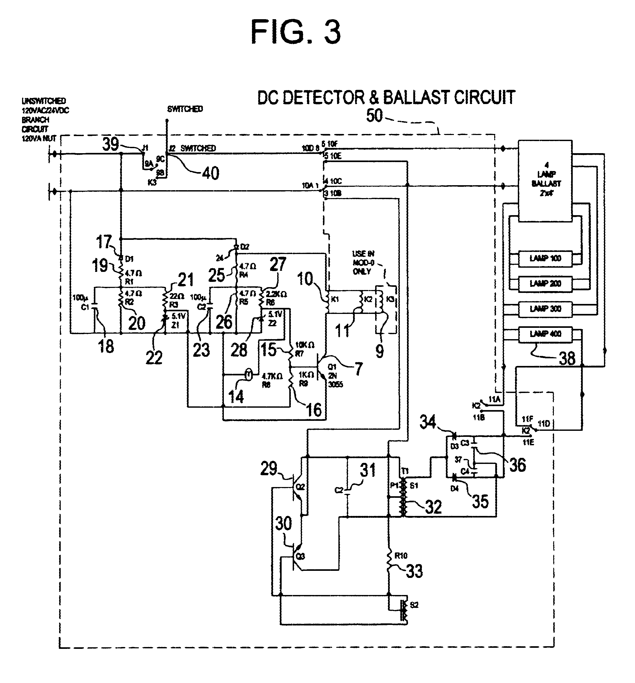
fig 104 two (2) lamp instant start ballast wiring diagrams for 2-lamp emergency operation (2´- 4´, 17- 40 w lamps only) wiring diagram for 1-lamp emergency operation emergency ballast and ac ballast must be fed from the same branch circuit typical schematics only. may be used with other ballasts. consult the factory for other wiring diagrams ...

Iota Emergency Ballast Wiring Diagram | Free Wiring Diagram
Ad Find Deals on Products in Ballasts on Amazon. 4 bulb ballast wiring diagram 4 lamp t12 ballast 4 lamp emergency ballast wiring diagram wiring diagram manual barbie games co. 4 Lamp T5 Ballast Wiring Diagram Lovely Wiring Diagram for. Each component ought to be placed and connected with other parts in specific way.

Replace T8 Ballast WITH Emergency Back-up - DoItYourself ...
Fluorescent Emergency Ballast Wiring Diagram - Wiring Diagram - Ballast Wiring Diagram Furthermore, Wiring Diagram gives you the time body by which the assignments are for being accomplished. You may be able to understand exactly if the projects needs to be finished, that makes it much simpler for you to effectively handle your time and effort.

Emergency Battery Ballast Wiring Diagram - Wiring Diagram ...
Choose the right wiring diagram to connect the ballast to the AC ballast and lamp. ... the emergency ballast and the AC ballast, the test switch has to be ...
Fluorescent Light Wiring Diagram For Ballast Inspirational ...
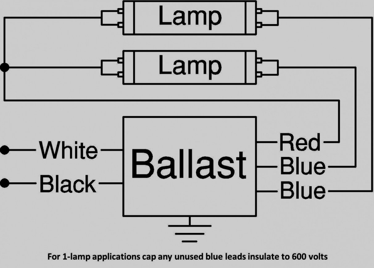
For wiring diagrams of ballasts not. The emergency ballast and ac ballast must be on the same branch circuit. The emergency ballast and a.c. Use the wire cutters to cut the wires connected to the sockets. Magnetic fluorescent ballast wiring diagrams. The 26 watt ballast shown below can be used for 1 or 2 lamps.

Emergency Light Ballast Wiring Diagram : Sign Ballast ...
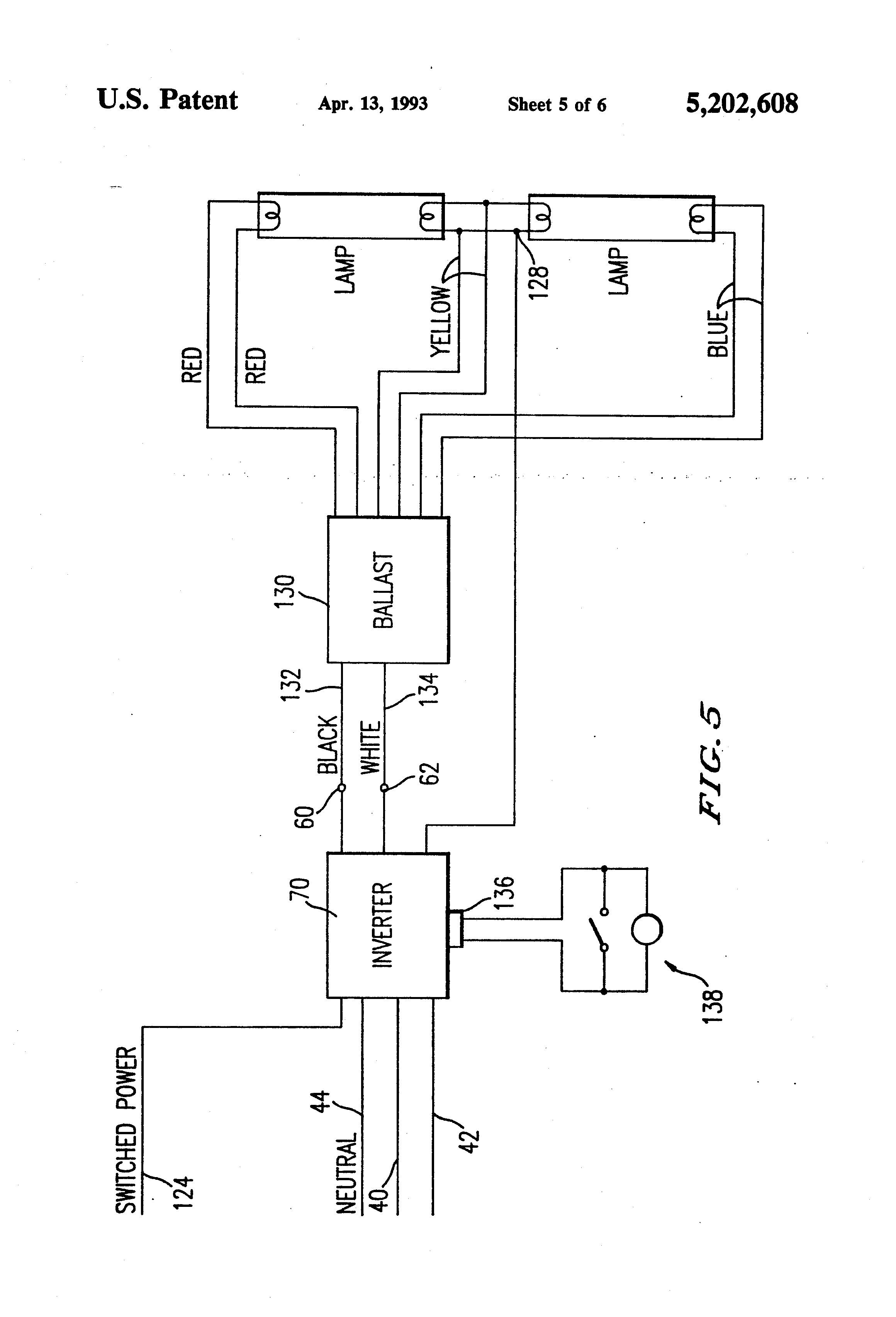
2 Remove or Short Ballast and Starter if present. EarthLED offers a complete selection of T8 and T12 LED tube lights that bypass traditional fluorescent ballasts. 4 lamp 8 foot conversion bracket for LED with ballasts disconnect. 25 shows a block diagram of an example system that uses an electronic ballast and embedded battery power in a compact fluorescent lamp with an intelligent ...
Iota Emergency Ballast Wiring Diagram Download | Wiring ...
Need Help? Chat with us now · A RAB support representative will respond soon

Panoramic view from the sky overlooking neighborhoods, recreational park, canal, bridges, shopping centers, a hospital, and medical center.
3.WIRING Refer to the wiring diagrams on the back page for the appropriate wiring of lamp(s) and ballast. Install in accordance with the National Electrical Code and local regulations. For additional wiring diagrams consult Customer Service. 4. INSTALLING THE THREADED BODY TEST SWITCH (TBTS)

Iota Emergency Ballast Wiring Diagram - Wiring Diagram ...
31 Iota Emergency Ballast Wiring Diagram Free Wiring The best option is always to use a verified and accurate Iota isl 54 Wiring Diagram that's provided from a trusted source. A good, traditional company that has a long track baby book of providing the most up-to-date wiring diagrams reachable is not hard to find.

Fluorescent Emergency Ballast Wiring Diagram | Free Wiring ...
T8 Fluorescent Ballast Wiring Diagram New T8 Electronic Ballast - Fluorescent Ballast Wiring Diagram. Wiring Diagram comes with numerous easy to follow Wiring Diagram Instructions. It is intended to aid all the average user in building a proper program. These directions will be easy to grasp and use.
Led Emergency Ballast Wiring Diagram - Wiring Diagram and ...
21 posts related to Led Rechargeable Emergency Light Circuit Diagram. Rechargeable Emergency Tube Light Circuit Diagram. Sf6 Circuit Breaker Control Circuit Diagram Pdf. Edm Circuit Diagram. Fbp 1 40x Fluorescent Emergency Ballast Wiring Diagram. Bodine Emergency Ballast Wiring Diagram.
Emergency Ballast Wiring Diagram - Wiring Diagram & Schemas
Ballast Sections: Pulse Start Metal Halide Standard Metal Halide HPS ballasts Brackets Wiring Diagrams Warranty Information · Wiring diagrams for Venture® HPS and remote ballast products are provided on this page. The ballast data tables in our catalog indicate the page number and reference ...


Comments
Post a Comment