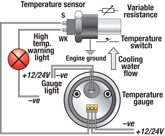
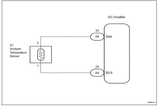
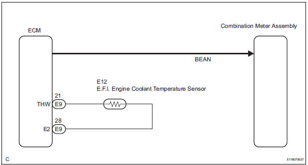
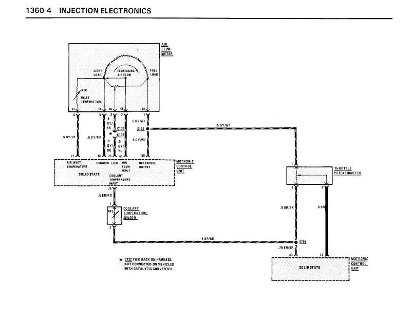
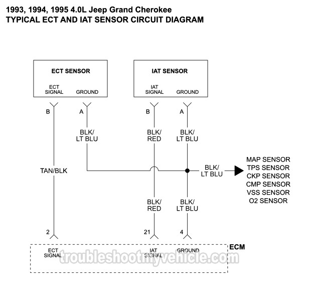
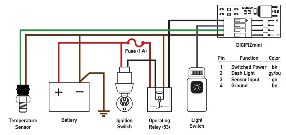
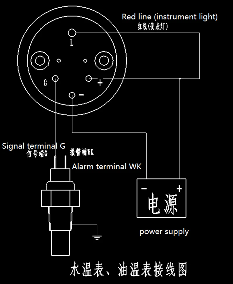
42 temperature gauge wiring diagram
Take a moment to familiarize yourself with the wiring diagram. It may help to open the high resolution image in another window, or print it out. Note that the pictures are from an earlier version of the Duet however the wiring guide steps are still valid. Edit . 3 comments . Add a comment . Add Comment Cancel . Post comment. Step 2 A Note on Fire Safety . WARNING: it … Wiring Diagrams. 01 Six Gauge Set Wiring Diagram. Six Gauge Set Wiring Diagram SNWH03 . All-American 3200/6400 Package Guide Rev 2/27/13. Download 3200 Wiring Instructions Rev 2/7/13. Download 6400 Wiring Instructions Rev 2/7/13 . Senders . SN11 Low Volt Light Rev 7/12/12. Download SN11 Low Volt Light Wiring Diagram 7/12/12 . SN20 Tachometer Filter
Today I am going to attempt installing an AEM water temp gauge on my e36 m3. I am very unfamiliar with wiring and electronics on cars. There is already a sensor installed on my thermostat housing that I believe will work with the AEM connector, if not I can remove this and install the sensor it came with. All the DIY's I've seen have installed the temp sensor near the throttle body cooling line. when my car was at my buddies shop he installed the sensor on the thermostat so I am going to attempt...
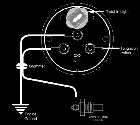
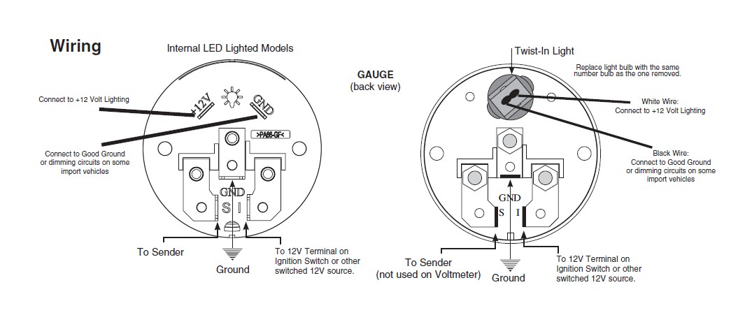
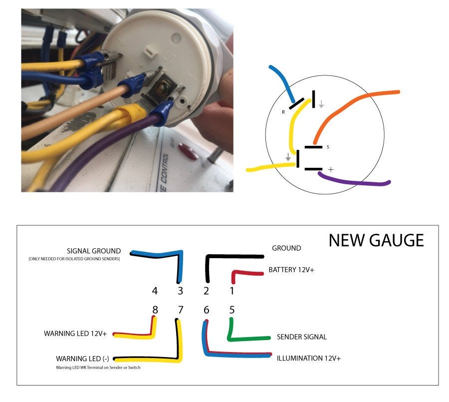
Temperature gauge wiring diagram
Electrical Wiring: Refer to the wiring diagram, Diagram G. Wire gauges in series from a positive (+) accessory to a source which is not already overloaded with fans, air conditioning, and such. The ground (Œ) wire is also run in series, including the light socket ground. The final ground run, using 14-gauge wire, should be connected to a good ... Just as the title says, I have a 96’ T100 with an electrical issue. I was driving 80 miles per hour on a 90 degree day Sunday and my A/C turned off suddenly most of my gauges went dead. I assumed it was a fuse and just decided to roll my windows down and chase it when I got home. I assumed it had something to do with my AC or my blower, so I replaced the fuse, turned off the air conditioning and the blower, turned the key to ACC, and the fuse blew right away before I even was able to start the ... TEMPERATURE GAUGE WIRING (Figure 3): 1. Disconnect negative (-) battery cable. 2. Using 18-ga. wire, connect the (G) terminal to a clean (rust/paint-free) ground surface near the temperature sender. 3. Using 18-ga. wire, connect the (I) terminal to a switched +12V source. 4. Using 18-ga. wire, connect the (S) sender terminal of the
Temperature gauge wiring diagram. Hi everyone, Recently picked up a 1990 240sx hatch that has a CA18DET swapped in. The car is in good shape but electrical is a basket case and the previous owner did not do the swap and admits knowing very little about the wiring. Essentially only the temp gauge, indicator symbols, and the little warning lights work on my gauge. I have no speedo or tach, battery, or gas showing. I believe they had to use the CA18DET engine harness wiring spliced into the OEM wiring. I was looking at diagram... TEMPERATURE GAUGE 1. Locate the original dark green wire found at location T-C in the fuse block bulkhead connector as shown on page 4 and remove it from the connector. Plug the loose terminal on the dark green wire (35A on page 3) from the Dash Side Gauge Harness Extension into the fuse block bulkhead connector at location T-C as shown on page 4. Vdo Gauges Wiring Diagrams - Page 3 - Wiring Diagram And Schematics vdo marine fuel gauge wiring diagram best of gauge sending. Ford Fusion Relay And Fuse Box Diagram - List Of Schematic ford escape fuse box location just wiring data rh ag skiphire co uk. VDO Spin-Lok™ Clamp or mounting bracket 1 5. A vehicle owner can wire a temperature gauge in his or her vehicle in a driveway or garage. Step 1. Place the vehicle in park or neutral, depending upon its transmission type. Set the emergency brake. Raise the hood and disconnect the negative battery cable with a socket. Refer to your owner's manual for the location of your existing ...
Jan 10, 2018 · Wiring diagrams VDO cockpit international (for engine coolant) The electrical oil temperature gauge has been designed for land-bound vehicles or.THE INSTRUCTIONS FOR INSTALLATION AND ELECTRICAL WIRING FOR THE INSTRUMENT KIT FOLLOWS. USE IS RESTRICTED TO 12 VOLT NEGATIVE GROUND ELECTRICAL SYSTEMS. Temperature Gauge (21/16" diameter) 1 6. Autometer Gauges Wiring Diagram Inspirational Wiring Diagram Auto - Autometer Gauge Wiring Diagram. Wiring Diagram consists of each illustrations and step-by-step directions that might allow you to definitely truly construct your project. This can be helpful for each the folks and for specialists who are looking to learn more on how to ... Working on my 83 C20. Based off of diagrams and what have you, the green temp gauge wire should come out of the firewall, and then connect somewhere on the engine to convey the reading. The only green wire that I have that fits the bill runs up above my transmission. Does anyone have any idea what I do with this? I haven’t had temp or oil pressure readings since I bought the truck, and I’m trying to rectify it on my own. Any suggestions? hours ago — Faria Gauges Wiring Diagrams used in a Faria Gauges Wiring Diagram electrical discharge machining method tend to be the core on the system.. Oct 2, 2012 — Download 2 58 short sweep gauge installation guide. And today this is the first picture wiring diagram for dolphin gauges. Our harnesses are ....
Figure 1-1 shows a Wheatstone bridge circuit diagram. Learn about Plug & Play Smart Load Cell Systems. ... One active strain-gauge element and one passive, temperature-sensing quarter-bridge element (dummy gauge). The active element is mounted in the direction of axial or bending strain. The dummy gauge is mounted in close thermal contact with the strain … 12.01.2015 · Kindly please help me with a complete wiring diagram for Alfa Romeo 155v6 2.5 167(AIC)..1995 to show the Bosch Motronic 88 pin outs and the location on the car of the ignition COTROL module.Thanks a mil and Happy New Year from Nairobi. #426. Paul Finney (Thursday, 06 January 2022 12:48) MANUAL #425. Seth (Tuesday, 04 January 2022 06:35) Could I … Transmission Temperature Gauge Wiring Diagram . Following the diagrams, make sure your Gauge has at least one ground wire and one positive wire. Connect positive wire to and ignition (on with key) power supply. The signal terminal needs to be connected tot he transmission temperature sensor/sender. Jan 26, 2020 · Temperature Gauge Wiring Diagram. Wiring Diagram January 26, 2020 02:52. Temperature Gauge Wiring Diagram Bobcat T200 Wiring Diagram Wiring Diagram Name. Temperature Gauge Wiring Diagram – wiring diagram is a simplified all right pictorial representation of an electrical circuit. It shows the components of the circuit as simplified shapes, and the aptitude and signal associates amid the devices.
Aug 15, · Autometer Pyrometer Wiring Diagram auto meter ficial site trade in any aftermarket gauges for credit on new autometer gauges 15 trade in trade up read more auto Autometer Pyrometer Wiring Diagram Isspro Electric Water Temp img source: diagramweb.net Autometer Pyrometer Wiring Diagram As Well As Temperature Gauge img source.
I want to wire two separate switches (both on the same circuit) in a 2 gang box. One will control 4 can lights, and the other will control 3 can lights. This is in my basement. The power will be feeding the switch box first. Hope this is clear. Any help or a diagram would be very helpful!
I recently bought a fairly cheap hot wire foam cutter from Amazon (before u say it I know I should have bought the proxxon, but I didn't want to invest to much into it yet as I'm not sure how much use I'll get after I've made my dungeon tiles) and the thing works just fine but the width of the cut is fairly substantial. From videos I've seen it doesn't have to be this way, so I was wondering is it the gauge of wire that is likely the culprit (I am willing to buy thinner wire) or is the wire too ...
Electric Temperature Gauge Wiring Diagram by Vallery Masson on April 1, 2021 01 six gauge set wiring diagram. All the wires at the connectors have alpha numeric addresses showing where the other end of the wire is located ac cording to the grid.
I really need to know the pinout (numbers) for the 2010 stereo harness. I have searched for about 3 1/2 hours and come up with absolutely nothing. I have a 2008 mustang that I am putting a 2010 steering wheel on, and am wiring up the controls for volume / track via a SWC module. I need to know what pins 18 and 19 are on the 2010 mustang, and which pins those would be on the 2008 mustang. any help at all would be appreciated more than you know!
Nov 21, 2020 · Temperature Gauge Wiring Diagram. Temperature Gauge Wiring Diagram from www.boatus.com. Print the electrical wiring diagram off in addition to use highlighters to trace the routine. When you use your finger or even stick to the circuit along with your eyes, it may be easy to mistrace the circuit. A single trick that I use is to printing the same wiring diagram off twice.
[http://www.wrxinfo.com/service\_manuals/](http://www.wrxinfo.com/service_manuals/) Been researching some torque specs for suspension stuff and was surprised about the amount of misinformation and confusion out there across forums and videos. Here ya'll go, hope this helps some of you DIYers.
the sender body, or backwards, the fuel gauge will read “FULL” when the temperature sender Refer to the wiring diagram, Diagram G. Wire gauges in series from a positive (+) Temperature: Needle to the temperature of the engine water.Using the expertise we’ve gained in developing specialized solutions for many of the world’s leading manufacturers, we offer a large portfolio of pressure and temperature sensors that we manufacture our sensors in our own ISO and TSO registered facilities ...
1998 ford escort blower motor wiring diagram [31 KB] 2000 ford explorer temperature gauge wiring diagram [17 KB] ford aerostar electronic engine control module wiring diagram [129 KB] ford anglia 100e 1953 1957 chassis wiring diagram [322 KB] mustang v6 2005 2007 fog light wiring diagrams [84 KB]
With my current sub, my car audio shop installed an 8 gauge wiring kit for it. I'm upgrading to the P500. I'm not fancy on installing things myself, so I'm trying to go the route of least work. Is the difference in power between 8 and 4 gauge worth it for a sub like this? Also, it's going into 17 Chevy Cruze LT. Thanks!
White Wire: Connect to +12 Volt Lighting. INSTALLATION INSTRUCTIONS. SHORT SWEEP ELECTRIC GAUGES. 2650-1079-00 Rev. C. Mounting. Replace light bulb with the same . number bulb as the one removed. These gauges can be mounted in-dash or in Auto Meter mounting solutions (panels, cups, pods, etc.). 2. 1 ⁄ 16" diameter gauges mount in 2. 1 ⁄ 16 ...
11.08.2017 · car temperature gauge wiring diagram; car tow bar wiring diagram; car tweeter wiring diagram; carburetor small engine diagram; case 1840 skid steer wiring diagram; case 420 skid steer wiring diagram; case 430 skid steer wiring diagram; case 450 skid steer wiring diagram; cat 236b skid steer wiring diagram ; cat 262 skid steer wiring diagram; cat 5e rj45 …
Temperature Gauge Wiring 1) Always disconnect the vehicle battery before wiring any gauge. 2) Connect a switched +12VDC power source to the post marked "I" on the back of the temperature gauge. 3) Connect a good chassis ground to the post marked "G" on the back of the temperature gauge.
Temperature Gauge Wiring Diagram. Jump to Latest Follow 1 - 3 of 3 Posts. H. hack67 · Registered. Joined Nov 17, 2009 · 9 Posts . Discussion Starter · #1 · Dec 31, 2009. I recently bought a 1967 Mustang Coupe 289 2V. ...
Vdo water temperature gauge wiring diagram. I installed the vdo oil pressure and temperature gauges in my 1970 vw but will give you the concept on installing them in any vehicle. Coolant temperature oil temperature oil pressure fuel level and speed. All in one digital display system. This is part 1 on how to install vdo gauges.
Smiths gauges made after 1964 have two terminals. Wiring diagram for smiths classic gauges a coupe of guys were discussing the wiring of ammeters on the yahoo. The side with only 1 plug fitted a voltage regulator ts7810cz 1a positive fixed voltage regulator to220 case from maplin. Triumph herald group so ive dug out this wiring diagram that ...
Trans Temp Gauge Installation: but an A-pillar gauge mount is available as a professional location to mount two gauges. diagramweb.net has a 2 & 3 gauge pod available Pictured below is a copy of the wiring diagram for the Autometer Transmission Temperature Gauge. STEP 4.
diagram g wiring diagram wiring of power and ground to each gauge illumination wiring and wiring of senders to each gauge. Find VDO Gauges Gauges, Analog with Water temperature Gauge Type and get Free Shipping on Orders Over $49 at Summit Racing!
Black 7 Color Celsius Oil Temperature Gauge Air Pressure Gauge Fuel Pressure Gauge Gauge Kit . Tachometer Wiring Diagrams Car Gauges Diagram Gauges . Pin On Automotive Lighting And Electrical . Pin On Products . Sponsored Ebay 52mm White Green Maxtow 250 F Differential Temperature Gauge Mt Wdv22 Diesel Trucks Fuel Pressure Gauge Gauges
3 Wire Coolant Temperature Sensor Wiring Diagram The two wires, a “5-volt reference”, and a “ground wire” go to the ECU, and the third wire “Earth Signal Wire for Temperature Gauge” goes to the cluster-mounted temperature gauge by providing an earth signal to the temperature gauge.
Does anyone have a wiring diagram for the fuel pump on a 2017 6.7? After a lot of googlefication all I can find is for 7.3, 6.0, and 6.2. I’m installing a kill switch run to an upfitter switch in the cab for theft prevention.
making alterations to wire harness. The included harness's black ... 250F Temperature gauge (1) 80 PSI oil pressure gauge (1) E-F fuel gauge ... deviate from assembly or wiring diagram. Always disconnect battery ground before making any electrical connections. IMPORTANT: ...
Temperature gauge troubleshooting begins with isolating the problem either to the gauge, sending unit, fuse or wiring. As with any electrical troubleshooting it is best to check all wiring connections are clean, tight and free of corrosion. The following process must be preformed with the ignition key turned to the "on" position.
TEMPERATURE GAUGE WIRING (Figure 3): 1. Disconnect negative (-) battery cable. 2. Using 18-ga. wire, connect the (G) terminal to a clean (rust/paint-free) ground surface near the temperature sender. 3. Using 18-ga. wire, connect the (I) terminal to a switched +12V source. 4. Using 18-ga. wire, connect the (S) sender terminal of the
Just as the title says, I have a 96’ T100 with an electrical issue. I was driving 80 miles per hour on a 90 degree day Sunday and my A/C turned off suddenly most of my gauges went dead. I assumed it was a fuse and just decided to roll my windows down and chase it when I got home. I assumed it had something to do with my AC or my blower, so I replaced the fuse, turned off the air conditioning and the blower, turned the key to ACC, and the fuse blew right away before I even was able to start the ...
Electrical Wiring: Refer to the wiring diagram, Diagram G. Wire gauges in series from a positive (+) accessory to a source which is not already overloaded with fans, air conditioning, and such. The ground (Œ) wire is also run in series, including the light socket ground. The final ground run, using 14-gauge wire, should be connected to a good ...








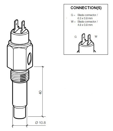
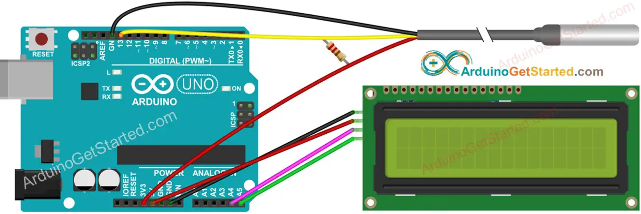


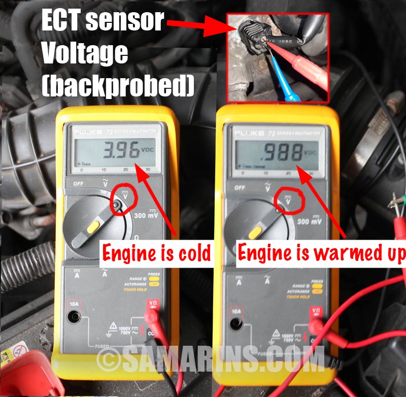


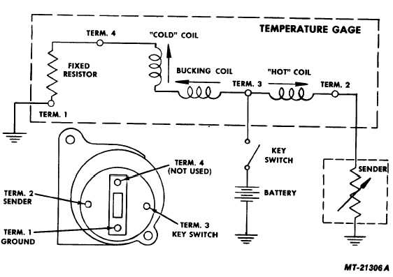
Comments
Post a Comment