40 fm transmitter block diagram
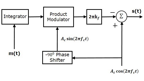
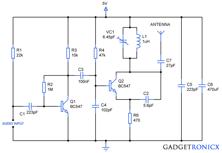
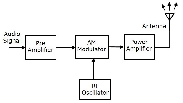
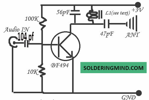
Fm Transmitter Block Diagram - Free Catalogs A to Z FM transmitter. Frequency Modulation is the process in which the frequency of the carrier signal is varied by the modulating signal while the amplitude remains constant. 8 hours ago FM transmitter FM Transmitter Block Diagram Direct Method. Using Reactance modulator direct method. Simple FM Transmitter Circuit Diagram and Making It on Breadboard A FM transmitter is a device that uses the principles of frequency modulation to broadcast sound supplied at its input. Typical FM transmitter design's usually follow the block diagram below; The signal strength of audio inputs into the transmitter is usually low therefore an amplifier is usually built...
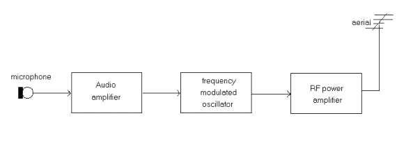
Transmitter Block Diagram | Frequency Modulated (FM) Transmitter · The Frequency generation stage (often known as the oscillator) defines the frequency on which the transmitter will operate. · The power amplification of the radio signal is carried out in the final stage of the block diagram. It makes the signal stronger so that it can be transmitted into the aerial.

Fm transmitter block diagram
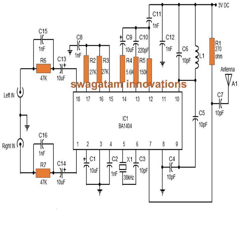
BA1404 FM Transmitter Circuit Diagram Stereo - Xtronic About the FM transmitter circuit with BA1404. The circuit formed by C1, L1, C2, C3 is a filter (optional) for transients that may come from our power supply. The RF coil is usually a critical component in FM transmitter assemblies, the ideal coil for this circuit is a 3.5 turn ferrite core found in FM radios. PDF D:\BH1415BLOCK.gul | [ FM MPX TRANSMITTER BLOCK DIAGRAM ] S1417F Fm mpx transmitter module block diagram. copyfrance@hotmail.com SECUGENE Co.,Ltd. Audio in l-r frequency. 1-1 SUMMARY This USB HOST MP3 player are stereo transmits (MP3, WMA file, etc) to FM radio Transmision Frequency are selectable 13CH(in... FM Transmitter Block Diagram with Explanation - Electronics and... Block diagram of a low level FM broadcast transmitter is shown in figure. The master oscillator generates the RF signal (carrier) required for But it must have the stability of a crystal oscillator since it is the part of a commercial transmitter. If the frequency of the master oscillator shifts, the output...
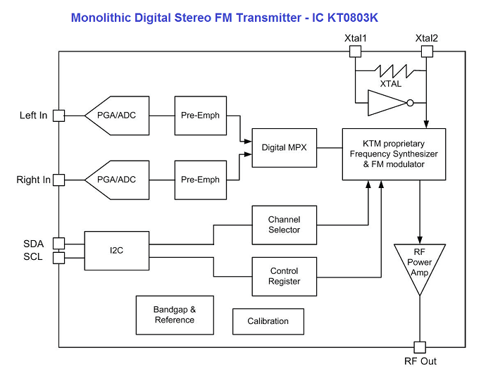
Fm transmitter block diagram. Design and implementation of low power FM transmitter Frequency modulation is used for sound broad casting in the VHF bands for VHF and UHF mobile systems and for wide band UHF and SHF radio relay systems.FM transmitters are used to generate high frequency signal.[2][1] Block diagram of FM transmitter. PDF Microsoft Word - DS069-8.doc | Transmitter Block Diagram This transmitter and receiver pair enables the simple implementation of a data link at distances up to 75 metres in-building and 250 metres open ground. Compatible with many other RF transmitter module footprints available. Transmitter Block Diagram. FM Transmitter Circuits | CircuitDiagram.Org This is a circuit diagram of FM microphone speak in microphone and hear your voice on FM receiver. Here is a schematic of a FM tracking transmitter circuit. The circuit can be operated with 1.5V battery (any size) and it will last longer because the current consumption of the circuit is only... Arduino FM Transmitter | IC KT0803K Block diagram FM Transmitter, I think every electronics maker may tried out. In this Project an FM Transmitter made out with KT0803K based board and it is controlled by famous Arduino UNO board. It transmits our voice through Frequency Modulation between 70MHz to 108MHz. IC KT0803K Block diagram.
FM Transmitter Block Diagram | Download Scientific Diagram This paper will explain FM communication simulations that use a guide between GNU Radio and RTL-SDR and are validated using a spectrum analyzer. The number of software in the telecommunications world allows us to make an FM simulation, one of the software is GNU Radio. Block diagram of AM transmitter and receiver with explanation Transmitters that transmit AM signals are known as AM transmitters. The basic block diagram of a basic superhet receiver is shown below. This details the most basic form of the receiver Quadrature FM detector: This form of FM detector block is widely used within ICs. IT is simple to implement and... FM TRANSMITTER BLOCK DIAGRAM|AM , FM, PM... - YouTube Transmitters with block diagrams General AM transmitter and theri function General FM transmitter and theri function General PM transmitter and theri function working of each blocks Plezzz like and subscribe my video. PDF MergedFile | Advantages of the FM Transmitters Radio Transmitters- Classification of Transmitters.AM Transmitter block diagram and explanation of each block. UNIT II SSB MODULATION: Frequency domain description, Frequency discrimination method for generation of AM SSB Modulated Wave, Hilbert Transform & its Properties...
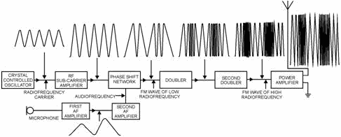
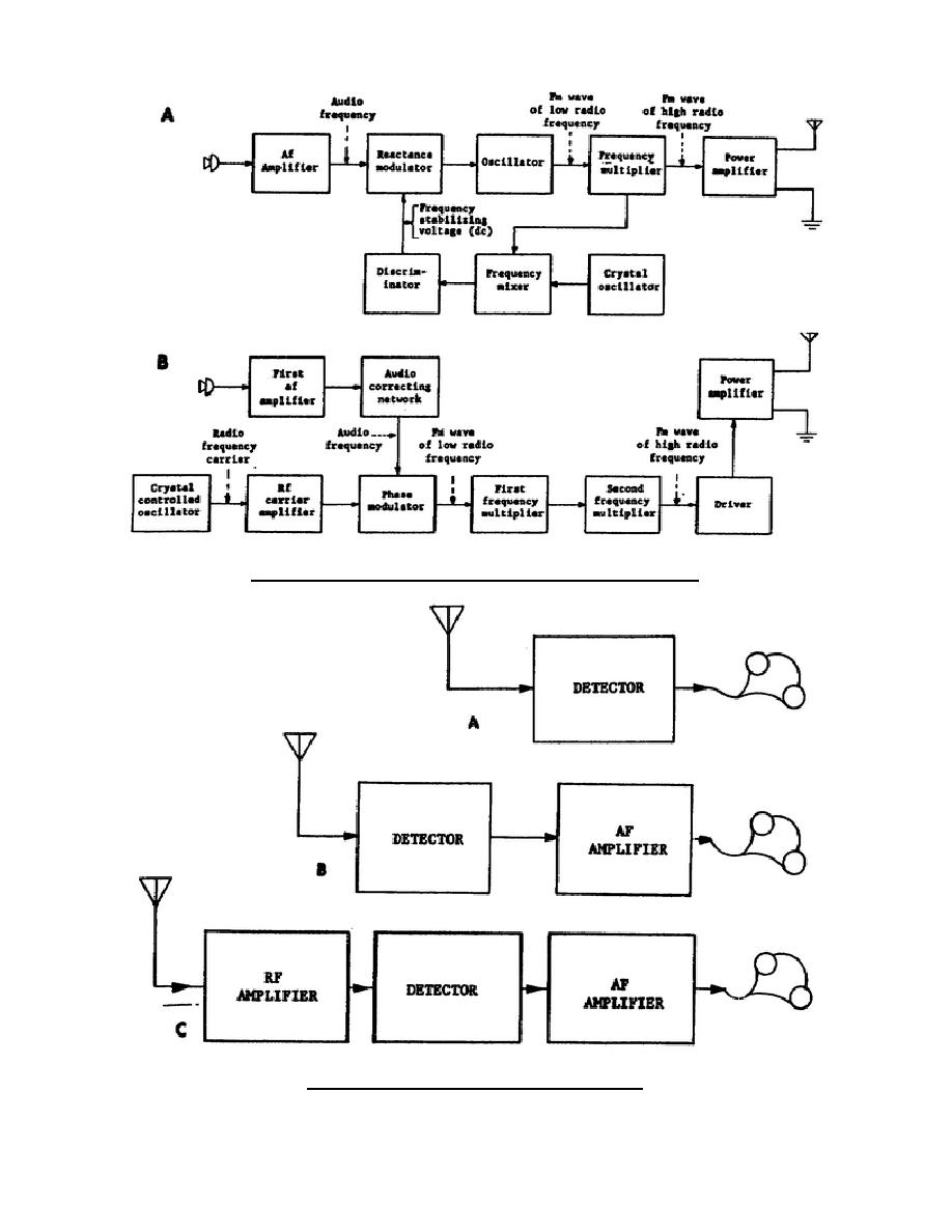
PDF Navy Electricity and FREQUENCY MODULATED TRANSMITTER In frequency modulation (fm) the modulating signal combines with the carrier to cause the frequency. Figure 2-6 is a block diagram of an fm transmitter showing waveforms found at various test points. FM Transmitter circuits with schematic diagrams An FM transmitter is basically a small gadget that can broadcast audio from a source on a selected frequency. FM Demodulator using PLL - This is a good circuit of an FM demodulator with a schematic diagram, a design of FM demodulator, and working of PLL with block diagram. PDF Audio File Transmission | FM Transmitter Figure 1. Software Defined Radio Block Diagram. Electrical and Computer Engineering, Cleveland State University. Figure 3. GNU radio framework structure 1. Practical Implementation using WBFM Modulation/Demodulation Scheme FM Transmitter In practical implementation the modulation... Fm transmitter and receivers 1. FM- TRANSMITTERS AND RECEIVERS By- Yogesh bhargawa M.Sc. 3rd sem. BBAU. 5. Input transducer transmitter channel receiver Output transducer noise Speech picture/data Information in Electrical form Information in original form Information source Block diagram of communication system.
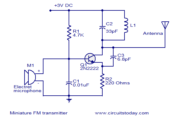
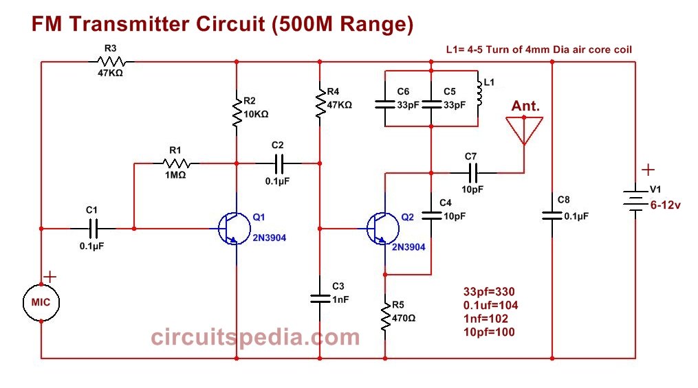
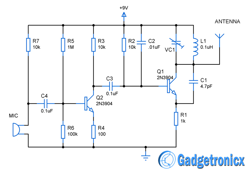
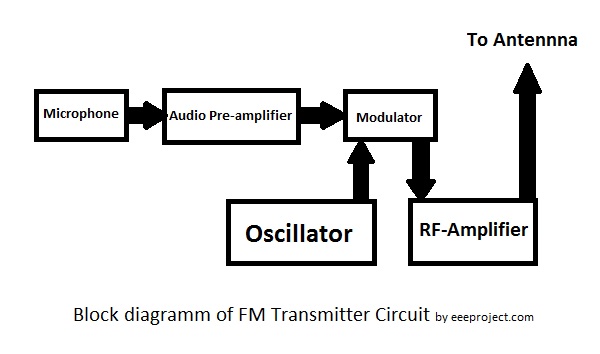
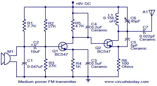
Block Diagram for FM transmitter circuit - EEE PROJECTS The FM transmitter (Frequency modulation) circuit is made up of a single transistor or a BJT. The FM Transmitter produces a range of VHF from 88 HZ to 108 MHZ. Block Diagram for FM transmitter circuit.
4. Transmitting and Receiving a Multimedia File using FM via USRP Non-Coherent FM Demodulation. It is also called as Complex Delay Line Frequency Demodulator derived using the blocks as shown. Ask your instructor to open, and then run the TX_FM_Music.slx file. Check the block diagrams for the transmitter (You will find no difference than the music...
FM Transmitter The block diagram of FM transmitter is shown in the following figure. The working of FM transmitter can be explained as follows. The audio signal from the output of the microphone is sent to the pre-amplifier, which boosts the level of the modulating signal.
PDF High Performance Digital FM Transmitter for Portable Devices. The QN8027 integrates a complete transmitter function, from stereo audio input to RF antenna port, for worldwide FM band personal area broadcasting. 1 functional block diagram.
BH1417 Stereo FM Transmitter Fig.1: block diagram of the Rohm BH1417F stereo FM transmitter IC. The text explains how it works. We first published an FM stereo transmitter in SILICON CHIP in October 1988 and followed this up with a new version in April 2001. Dubbed the Minimitter, these earlier versions were based on the...
Figure 2. FM Transmitter Block Diagram Frequency Modulation (FM) is a form of modulation in which changes in the carrier wave frequency correspond directly to changes in the baseband signal. A block diagram description of an FM transmitter follows.
Fm Broadcasting Block Diagram Discussion related to Frequency Modulation (FM) based Transmitter and Receiver of a Stereo System explained with fm block ... FM Broadcasting with the understanding of the Block Diagram of FM Transmitter is presented. This is a video series for the ...
fm transmitter block diagram datasheet... - Datasheet Archive FM Transmitter Block Diagram Initial , SN761633 FM STEREO RADIO WITH TRANSMITTER SLES210A OCTOBER 2007 REVISED DECEMBER 2007 1 FEATURES Single-Chip FM Stereo Radio and Transmitter FM Stereo MPX [Receive (Rx , receiver and transmitter IC...
FM Transmitter Block Diagram, Working Principle... - ETechnoG FM transmitter circuit is used to produce and transmit the Radio Frequency signal wirelessly. You can see, in the block diagram of the FM Transmitter, the first block is the Microphone. The microphone is a Transducer which can convert the sound energy into an audio signal in the form of...
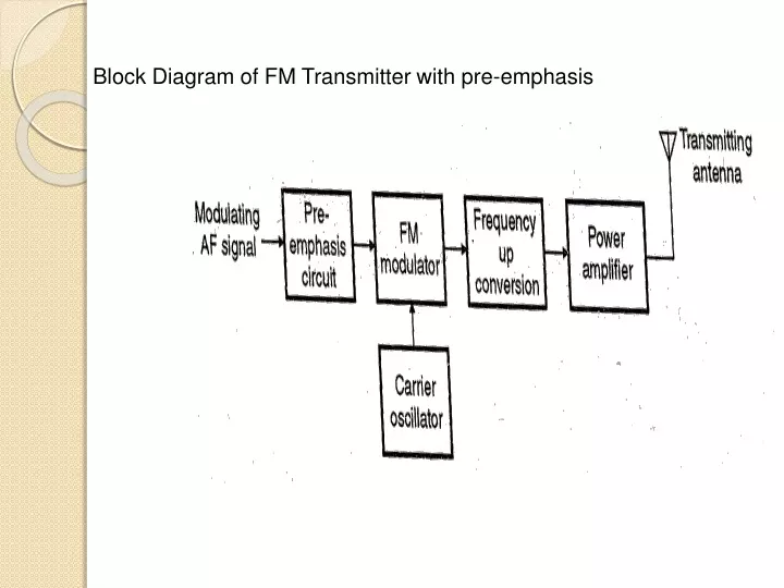
Block Diagram of FM Transmitter In the telecommunication, the frequency modulation (FM) transfers the information by varying the frequency of the carrier wave according to the The following image shows the block diagram of the FM transmitter and the required components of the FM transmitter are; microphone, audio...
FM Transmitter Block Diagram with Explanation - Electronics and... Block diagram of a low level FM broadcast transmitter is shown in figure. The master oscillator generates the RF signal (carrier) required for But it must have the stability of a crystal oscillator since it is the part of a commercial transmitter. If the frequency of the master oscillator shifts, the output...
PDF D:\BH1415BLOCK.gul | [ FM MPX TRANSMITTER BLOCK DIAGRAM ] S1417F Fm mpx transmitter module block diagram. copyfrance@hotmail.com SECUGENE Co.,Ltd. Audio in l-r frequency. 1-1 SUMMARY This USB HOST MP3 player are stereo transmits (MP3, WMA file, etc) to FM radio Transmision Frequency are selectable 13CH(in...
BA1404 FM Transmitter Circuit Diagram Stereo - Xtronic About the FM transmitter circuit with BA1404. The circuit formed by C1, L1, C2, C3 is a filter (optional) for transients that may come from our power supply. The RF coil is usually a critical component in FM transmitter assemblies, the ideal coil for this circuit is a 3.5 turn ferrite core found in FM radios.












Comments
Post a Comment