41 smoke detector wiring diagram pdf
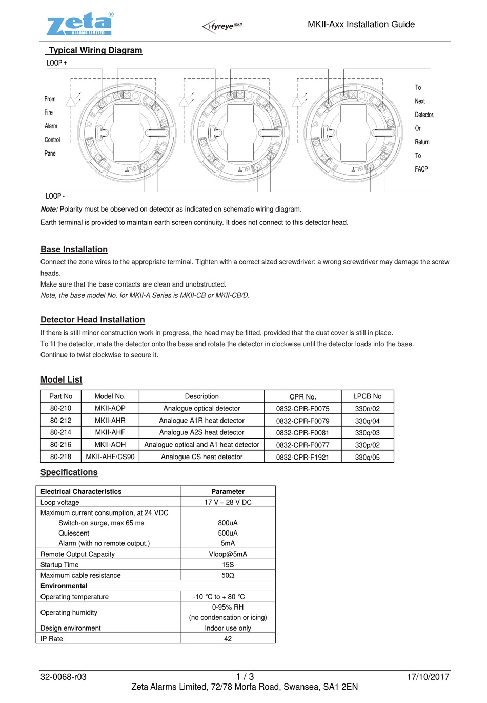
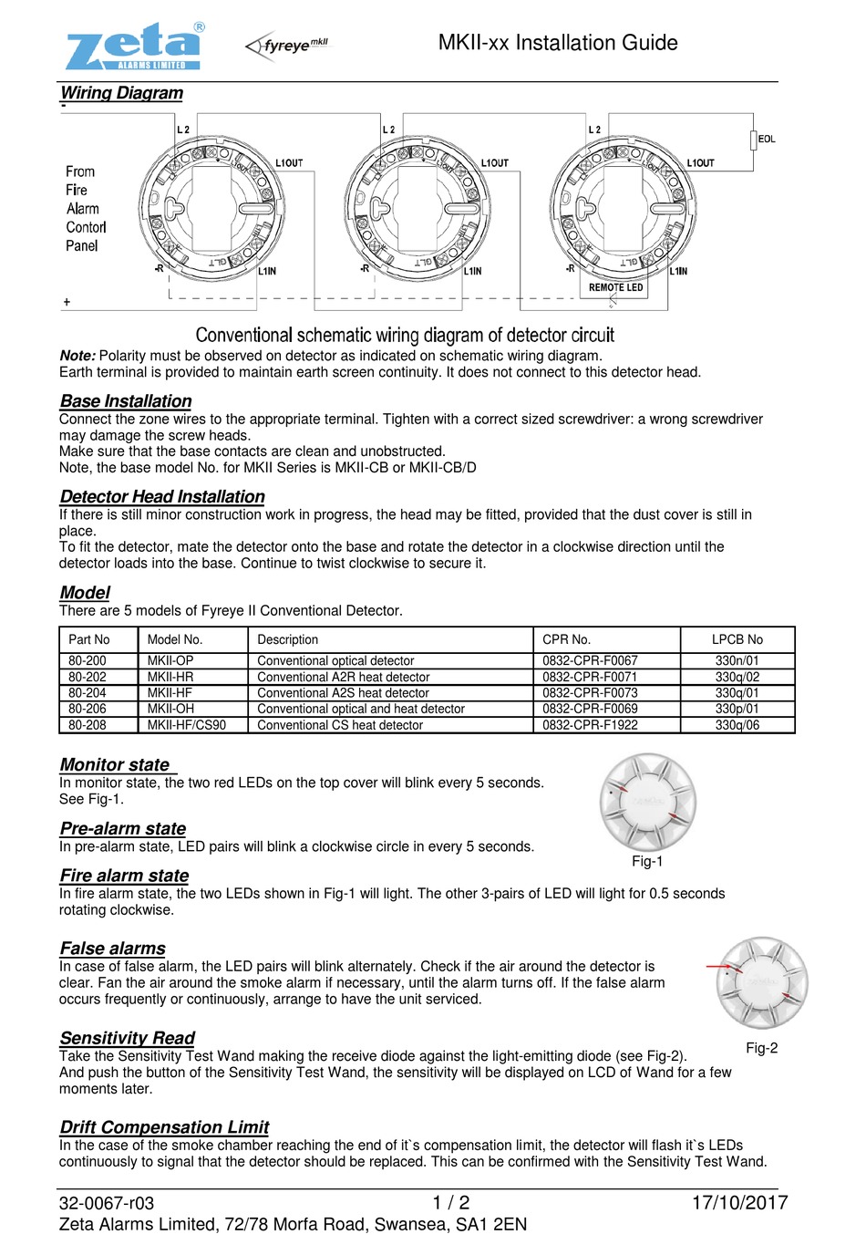
PDF Photoelectric Smoke Detector Installation Wiring Diagram flash, it indicates the non-functioning of the detector or faulty wiring. Re-check the wiring or replace the detector if necessary. 3. Allow smoke from a cotton wick or a test smoke aerosol to enter the detector-sensing chamber for at least 10 seconds. When sufficient smoke has entered Smoke Detector Wiring Diagram Installation Guide - Wiring ... Smoke Detector Wiring Diagram Installation Guide Wiring Diagram Line Uncategorized. ... Smoke detector installation guide mct423 wireless user manual inst instr new pdf visonic wiring diagram ea318 photoelectric manualzz 8dl500 smart sensor heat and honeywell mkii typical mct425 de3642 0 esl sentrol 429 449 428 448 series instructions siemens ...
OP921 Smoke Detector, Installation Instructions ... OP921 Smoke Detector, Installation Instructions - Installation Instructions - OP921. Fire - Addressable detectors and bases. English. Installation Instructions. Valid. 2020-10-02. A6V10323928_en. A6V10323928. S54320-F4-A2.
Smoke detector wiring diagram pdf
PDF WIZMART NB338 Photoelectric Smoke Detector Installation ... WIZMART NB338 Photoelectric Smoke Detector Installation Wiring Diagram TYPICAL WIRING DIAGRAM Figure 1(a) shows the typical wiring diagram of the 2-wire multiple-station smoke detector system. INITIATING LOOP EN54 LISTED COMPATIBLE CONTROL PANEL +-FIRST DETECTOR BASE LAST DETECTOR BASE EOL RESISTOR 5 2 5 2 61 34 6 1 3 4 +-REMOTE INDICATOR CLASS ... PDF D4120 Duct Smoke Detector - System Sensor As with our duct smoke detectors, all duct smoke detector accessories are UL listed. Ordering Information Part No. Description D4120 4-wire photoelectric low-flow duct smoke detector Accessories D4S 4-wire photoelectric sensor component only ETX Metal exhaust tube duct width 1ft (0.3m) D4P120 4-wire photoelectric power board component PDF ESL 700 Series Conventional Smoke and Heat Detector ... 721U Two-wire photoelectric smoke detector, with remote test input and remote alarm/trouble LED output 721UT Two-wire photoelectric, with rate-of-rise heat detector ... to the appropriate terminals according to the wiring diagrams (see Figure 6 or Figure 7). 3. Dress the wiring neatly, and then verify that the continuity
Smoke detector wiring diagram pdf. PDF r-‖¨ ?c " ™"‖'?v‥'‥—。?c‥‐。'‐-?h—'"‐〃〃‐"‥‖— r-‖¨ ?c " ™"‖'?v‥'‥—。?c‥‐。'‐-?h—'"‐〃〃‐"‥‖— 〕‥《-‐'"—©RRW ... PDF Photoelectric SD119 series Smoke Detector Installation ... Installation Wiring Diagram TYPICAL WIRING DIAGRAM Figure 1.a shows the typical wiring diagram of 2-wire multiple-station smoke detector system. The maximum number of smoke detector installed in DO NOT USE LOOPED WIRE UNDER TERMINALS 2 AND 5 BREAK WIRE RUN TO PROVIDE SUPERVISION OF CONNECTIONS Figure 1.b shows the typical wiring diagram of 4 ... PDF Installer's Wire Guide - Fire Alarm Resources Wiring diagrams provided herein are for information and reference only and ... (configured for 2-wire smokes) Table C-2: 0 SIGA-UMs or SIGA-MABs 83 Table C-3: 1 to 5 SIGA-UMs or SIGA-MABs 84 ... Signature Series:Signature Series: the world's first truly intelligent multisensor smoke detector PDF Smoke Detector (ESL) Sentrol 429-449-428-448 Series provided (see Diagram 5). All ESL smoke detectors are shipped with a plastic dust cover for use in areas where construction is on-going. Smoke detectors will not work with the dust cover in place. Remove the dust cover when installation is completed, prior to testing. Smoke Detector Placement and Spacing
Wiring Smoke Detectors New Construction : Wiring Smoke ... Wiring Smoke Detectors New Construction : Wiring Smoke Alarms Diagram. 2 Wire Smoke Detector Wiring Diagram,How To Wire Smoke Detectors In Parallel,How To Replace A Hardwired Smoke Detector,4 Wire Smoke Detector Wiring Diagram,Hard Wire Smoke Detector Keeps Going Off,How To Wire A Smoke Alarm To Lighting Circuit,Wiring Smoke Detectors New Construction,Smoke Detector Wiring Diagram Pdf,Wiring ... Smoke Detector Wiring 101 - DoItYourself.com A hardwired smoke alarm installation involves wiring one of the smoke detectors (closest to the voltage source) to a 120 VAC breaker in the main electric panel or tapping from a 120 V electrical box, wiring it using a 14/2 cable with a black (live), a white (neutral), and a ground wire, as shown by the diagram in Figure 5. PDF INSTALLATION AND MAINTENANCE INSTRUCTIONS Series FIGURE 3B: WIRING DIAGRAM, 4W-B AND 4WT-B AUX OR SMOKE ... 2 I56-1800-014 02-02. 2-WIRE I3 DETECTOR WIRED IN STYLE D CONFIGURATION: CAUTION Any 2-wire i3 smoke detector (2W-B, 2WT-B, 2WTA-B, or 2WTR-B) wired in the Style D initiating device circuit (IDC) configuration requires the use of a 2W-MOD2 module. This is because fire alarm control ... D4120 Duct Smoke Detector Wiring Diagram System sensor smoke detector wiring diagram System Sensor Convention 4 Wire Duct Smoke Detector D4120 Wiring Fancy. Smoke detectors designed for use in air duct systems are used to sense the presence of smoke in the duct. This unit senses smoke in the most challenging conditions operating in airflow speeds of 100 to 4000 feet per.
PDF detectors including all RW- Series, SM- Series and SL ... following wiring diagrams are applicable only to compatible, current limited, UL Listed remote accessories from Air Products and Controls. Use of any other devices may result in damage to the duct smoke detector, potential injury, and will void any applicable warranties. SL-2000 Series Duct Smoke Detectors * NOTE: PDF D355PL Duct Smoke Detector Northford, CT 06472 Smoke introduced into this air duct system will be distributed throughout the entire building. Smoke detectors designed for use in air duct systems are used to sense the presence of smoke in the duct. Model D355PL Air Duct Smoke Detector utilizes photoelectric technology for the detection of smoke. This detection method, when combined with an ef- Wiring Diagram For Hardwired Smoke Detectors For details on connecting smoke detectors and other devices to a typical alarm panel, see Ademco Vista 20P Wiring Diagram. A hard-wired smoke or carbon monoxide (CO) alarm is wired to a V household electrical circuit and is connected to other detectors throughout your home. Hard-wired smoke and carbon monoxide alarms sound simultaneously, on ... PDF Smoke Alarm 755psma4 Interconnecting Smoke Alarms HOW INTERCONNECTED ALARMS FUNCTION • Interconnecting smoke alarms is a method of joining a series of alarms so that if any one alarm senses smoke, all the connected alarms will operate (alarm). • A 9 V signal is applied to the interconnect wire (referenced to neutral) to alarm all the other interconnected alarms.
PDF Reflective Optical Beam Smoke Detector User Guide Optical Beam Smoke Detector ... Wiring Diagram For connection of a single conventional Detector to a zone: Note 1 - This component is the Fire Resistor, and its value is specified by the Fire Control Panel Manufacturer. For US installations it is typically a short circuit.
PDF 4098-9685, -9686, -9688, -9755, -9756 Duct Detector/Sensor ... detect smoke in air ducts. The 4098 Duct Detector/Sensors are available in the following configurations: • 4098-9685 Two-Wire Duct Detector supplied with the 4098-9601 Photoelectric Detector • 4098-9686 Four-Wire Duct Detector supplied with the 4098-9601 Photoelectric Detector
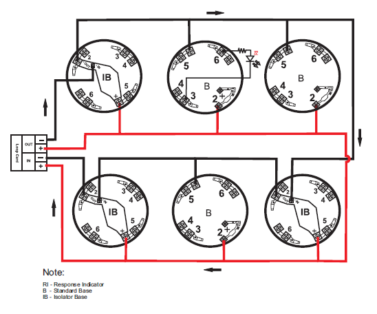
PDF Installation Manual Detector Bases: PAD100-IB, PAD100-RB ... PAD100-PD: Photoelectric Smoke Detector PAD100-PHD: Photoelectric Smoke / Heat Detector LasPAD100-HD: Heat Detector PAD100-CD: Carbon Monoxide Detector 2a. Field Wiring Diagram(s) for PAD100-IB Typical field wiring diagrams for the Signaling Line Circuit (SLC) are shown in FIGURE 1. The SLC supports NFPA wiring Class B, A and X.
Smoke Detector Wiring Diagram Pdf - Studying Diagrams Smoke detector wiring diagram pdf. Circuit diagram esser smoke detector wiring diagram. Click about Set Line Hops in the SmartPanel to show or hide line hops at crossover points. The detector housing shall be UL listed per UL 268A specifically for use in air handling systems.
PDF Two- and Four-Wire Conventional Smoke Detectors two-wire w/integral heat detector, output for remote LED 741UT Smoke detector head only, photoelectric, four-wire, w/integral heat detector, alarm relay (N.O.) output and output for remote LED 701U Smoke detector base, 3 terminals, 6 in. dia. 702U Smoke detector base, 6 terminals, 6 in. dia. (required for use with the 706U1B Remote LED) 204-12 ...
PDF Smoke Detector Manual (SSSD1) - SimpliSafe smoke detector is designed to give early warning of developing fires with an alarm sound from its built-in siren. These sirens can provide precious time to escape before a fire spreads. However, the smoke detector makes such pre-warning of fire possible only if the smoke detector is located, installed, and
PDF 4098 Detectors, Sensors, and Bases Application Manual Each detector/sensor is capable of providing up to 900 square feet (84 square meters) of coverage, depending on the following: Requirements of local codes. Results of engineering evaluation. Special Considerations Overview Special Considerations for Smoke Detectors and Sensors Smoke Detector/Sensor Applications
PDF Advanced Fire Training Manual Advanced Fire Training Manual Manual #8700055—Rev H 5/17 Potter Electric Signal Company, LLC St. Louis, MO Customer Service: (866) 240-1870 • Technical Support: (866) 956-1211 • Fax: (314) 595-6999
PDF INST APD0194 I090317 (SL-2000 Series Installation ... The SL-2000 Series smoke detector is fitted with a mounting base that will accept an ionization smoke detector head model 55000-225APO or photoelectric smoke detector head model 55000-328APO. The duct unit supports two sets of form "C" alarm contacts, one form "A" alarm contact and one form "C" trouble contact. The
PDF INSTALLATION INSTRUCTIONS - Hochiki America Connect wiring to the bases as shown in the wiring diagrams that follow. Detectors and bases may be mixed on the same initiating loop as long as the number of two-wire powered detectors does not exceed the specifications of the control panel (see Figure 2 below) SMOKE DETECTOR DATA BUILT-IN TEST FEATURE 135°F(SLR-24H only) 30/ZONE 17.7-30.0 ...
Interlinked Smoke Alarm Wiring Diagram - schematron.org BRK hardwired Smoke Alarms are designed to be mounted on any standard wiring junction box to a 4-inch (10 cm) size, on either the ceiling or wall. Connecting 2 Wire Smoke Detectors. Follow the specific fire alarm schematic supplied by the smoke detector manufacturer to make connections. A smoke detector wiring diagram is normally included with ...
PDF ESL 700 Series Conventional Smoke and Heat Detector ... 721U Two-wire photoelectric smoke detector, with remote test input and remote alarm/trouble LED output 721UT Two-wire photoelectric, with rate-of-rise heat detector ... to the appropriate terminals according to the wiring diagrams (see Figure 6 or Figure 7). 3. Dress the wiring neatly, and then verify that the continuity
PDF D4120 Duct Smoke Detector - System Sensor As with our duct smoke detectors, all duct smoke detector accessories are UL listed. Ordering Information Part No. Description D4120 4-wire photoelectric low-flow duct smoke detector Accessories D4S 4-wire photoelectric sensor component only ETX Metal exhaust tube duct width 1ft (0.3m) D4P120 4-wire photoelectric power board component
PDF WIZMART NB338 Photoelectric Smoke Detector Installation ... WIZMART NB338 Photoelectric Smoke Detector Installation Wiring Diagram TYPICAL WIRING DIAGRAM Figure 1(a) shows the typical wiring diagram of the 2-wire multiple-station smoke detector system. INITIATING LOOP EN54 LISTED COMPATIBLE CONTROL PANEL +-FIRST DETECTOR BASE LAST DETECTOR BASE EOL RESISTOR 5 2 5 2 61 34 6 1 3 4 +-REMOTE INDICATOR CLASS ...








Comments
Post a Comment