43 Air Brake Valve Diagram
Bendix Dash Valve Diagram - schematron.org Bendix Dash Valve Diagram. air brake valves and electronic controls. (ABS Information and diagrams are provided for guidance only. DASH & TRACTOR PROTECTION VALVES. Bendix® Valves. Genuine Bendix® Valves. Valves direct the flow and release of air throughout an air brake system a big job for the network of compact. schematron.org AIR-BRAKE (). Williams Air Brake Valves - proportioning valve diagram my ... Williams Air Brake Valves - 9 images - diagrams of brake proportioning valve my wiring diagram, williams air control valve,
Hydraulic brake - Wikipedia When the brake pedal is applied, the movement opens an air valve which lets in atmospheric pressure air to one chamber of the booster. Since the pressure becomes higher in one chamber, the diaphragm moves toward the lower pressure chamber with a force created by the area of the diaphragm and the differential pressure. This force, in addition to the driver's foot force, pushes …
Air brake valve diagram
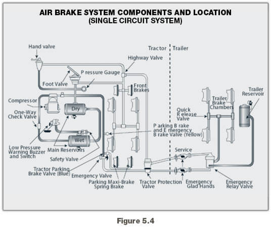
Air Brake Manual - SGI The five main components of an "elementary" air brake system and their purposes are the compressor, reservoir, foot valve, brake chambers, and brake shoes and drums or brake rotors and pads.. You must have an Endorsement A specified on your licence to operate a vehicle equipped with an air brake system. The endorsement is not required when operating a Class 3 or 5 vehicle licensed as a ... PDF Air Brake System Troubleshooting I With the introduction of spring brakes, anti-compounding and 121 air brake systems, because a valve is leaking air out of its exhaust, does not mean the valve is at fault. If a spring brake is leaking from the the spring brake to the service brake side, that air will travel back up the service line and out the exhaust of the ... International Air Brakes Series Air Brakes Series Welcome to the International® Air Brakes Series. The following DVD training series covers complete air brake fundamentals. It is designed to provide all the technical knowledge and skill necessary to diagnose and repair this brake system. This series is divided into six programs. The first program covers
Air brake valve diagram. 2010 Chevrolet Silverado fuse diagram — Ricks Free Auto ... 2018-09-08 · 19 TRANS IGN 1 Fuse 15A Transmission Control Module (TCM) (M30), 1-2 Shift Solenoid (SS) Valve, 2-3 Shift Solenoid (SS) Valve, 3-2 Shift Solenoid (SS) Valve (M30), Torque Converter Clutch (TCC) Solenoid Valve (M30), Torque Converter Clutch Pulse Width Modulation (TCC PWM) Solenoid Valve, Input Speed Sensor (ISS), Front Drive Axle Actuator, Automatic … How Air Brakes Work - HowStuffWorks Charging: The system must be pressurized with air before the brakes will release.At rest, the brakes remain engaged. Once the system reaches its operating pressure, the brakes are freed and ready to use. Applying: As the brakes are applied, air pressure decreases.As the amount of air decreases, the valve allows air back into the reservoir tanks, while the brakes move to the applied position. AIR SYSTEM PIPING DIAGRAMS Pre-121 Trailer Air Systems Cracking Pressure – The minimum amount of air pressure (in psi) required to open an air valve. Protected Reservoir System – A spring brake control valve (SBCV) option using integral one-way check valves for two reservoir systems that assures the loss of one reservoir will “protect” the other reservoir. Bendix Foot Valve Diagram - wiringall.com Bendix valves, compressors, air dryers, wheel end components and more, call 1- AIR-BRAKE or visit wiringall.com Some guys use. Bendix valves, compressors, air dryers, wheel end components and more, call 1- AIR-BRAKE or visit wiringall.com Some guys use. just replaced the air brake control/safety valve on a freightliner old routing diagram for an old truck be?
Learn About Cars & How to Work on Them - AutoZone Your brake pads and rotors help your vehicle make safe stops, so it’s important to replace them when necessary. Use this guide to help you get started replacing brake pads and rotors. Read More . Why is My Check Engine Light On? Learn 5 common causes of a lit check engine light, and what you can do to take care of it. Read More . Tune-Up Checklist. Regular vehicle … Brakes | The Railway Technical Website | PRC Rail ... The diagram in Figure 1 shows the principal parts of the air brake system. Figure 1: Schematic of air brake system. The air is drawn into a compressor and stored in a main reservoir at 7-10 bar (100-140 lbs/sq.in). Compressed air from the main reservoir is distributed along the train through the main reservoir pipe. AIR BRAKE SYSTEM TROUBLESHOOTING With the introduction of spring brakes, anti-compounding and 121 air brake systems, because a valve is leaking air out of its exhaust, does not mean the valve is at fault. If a spring brake is leaking from the the spring brake to the service brake side, that air will travel back up the service line and out the exhaust of the ... Tractor Air Brake System Explained This module can be used in lieu of the system park and trailer park valves shown in the diagram. The 4-sided dash valve button labeled system park (pp-1) is used for parking brakes. In the out position, it exhausts the spring brake pressure signal to the tractor spring brake relay valve (r-14) which in turn exhausts the tractor spring brake air ...
Air Brake Relay - How it Works. Air braking systems and ... A more detailed look at the air braking system, in particular with this video at the air brake relay.Relays are fitted to an air braking system for larger ve... Home - Bendix Marketing Center The Control System: Dual Circuit Brake Valves 19 Actuators 20 Foundation Brakes: Drum Brakes (aka S-Cam) 21 Foundation Drum Brakes 22 Air Disc Brakes 23 Slack Adjusters 24 Quick Release, Ratio & Modulating Valves 25 Relay Valves 26 Push-Pull Control Valves 27 Spring Brake Valves 28 Lever-Operated Control Valves 29 Additional Control Valves 30 Air Brake Valves: AnythingTruck.com, Truck & Trailer Parts ... Air Brake Valves for Trucks and Trailers. AnythingTruck.com is a distributor of name-brand air brake parts. This includes air brake valves made by Bendix, Meritor, Midland/Haldex, and Sealco, and we've made these valves available to the public at discounted prices. We also offer many aftermarket replacement valves from companies like Velvac and ... Air Brake System - Parts, Working, Diagram, Principle, Advantages air foot valve diagram. When the driver applies the brakes, depressing the treadle partway, the foot valve will automatically maintain the application air pressure without the driver having to adjust the pressure of his foot on the treadle. Releasing the treadle allows the application air to be released through the exhaust ports into the atmosphere.
Air Brake Handbook
Where can I See my Freightliner air brake system diagram ... With the introduction of spring brakes, anti-compounding and 121 air brake systems, because a valve is leaking air out of its exhaust, does not mean the valve is at fault. If a spring brake is leaking from the the spring brake to the service brake side, that air will travel back up the service line and out the exhaust of the next valve back.

Article: The Brake System – The Clipper Air Brake System ...
Full Functioning Valve (FF2) - Haldex A true single valve system for single and tandem axle trailers. Technical Tip TRUE NEW GENERATION VALVE Haldex has developed a true, single trailer air-system valve that combines the functions of outdated 2- and 3-valve systems. The Full Function Valve (FF2) offers OEM, Fleets and Owner/Operators: › Economical one valve approach for single

A general layout of a truck air brake system. | Download ...
37 air brake valve diagram - Diagram Online Source Air brake valve diagram. This video is about Dump Valve Install. i didn't do a good job because i wasn't really the one that put it in.. thanks Carl and Cody. Air compressor. This component produces air for the brake system. Powered by the vehicle's engine, the air compressor draws in air at normal pressure and forces it into a much smaller ...
air brake
M1082 Air Brake Valves(s) Diagram? Midland/Haldex ... On the M1082 trailer there is a valve going into the air tank. It's not like the setup on the trucks, obviously. It has a single "Supply" inlet (the second is capped) which is fed by service air and a "Control" inlet that t's off to emergency and the brakes. There is an internal airway ("Control" side) that retains a small spring and plunger.

Simple tractor-trailer system - SGI
Air brake (road vehicle) - Wikipedia Highly simplified air-brake diagram (does not show all air reservoirs and all applicable air valves) 1 Air compressor 7 Park brake hand control valve 2 Pressure regulator 8 Park brake safety release valve 3 Air dryer 9 Brake foot valve 4 Regeneration reservoir 10 Front air-brake chambers 5 Four-way protection valve 11 Brake-relay valve and load-sensing valve 6 …

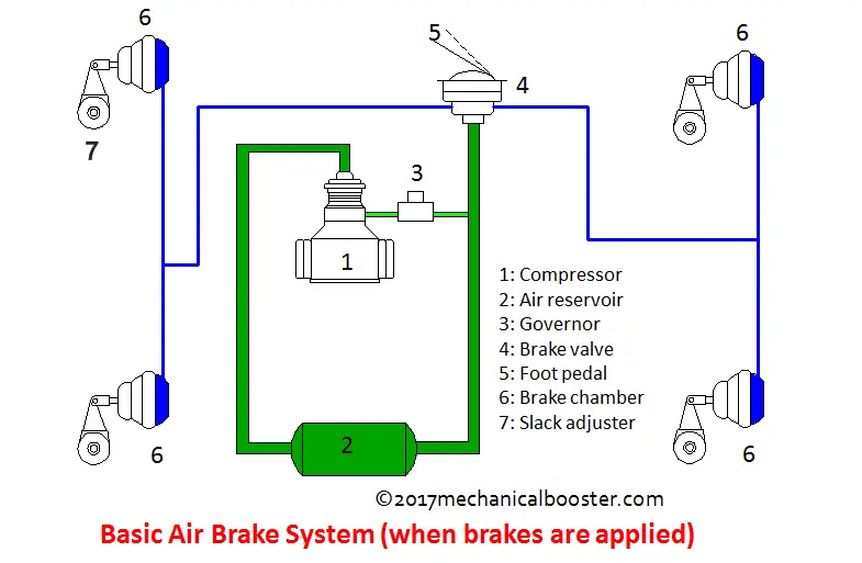
Basic air brake system - SGI
Bendix SR-7 SPRING BRK MODULATING VALVE User Manual DESCRIPTION. The Bendix ® SR-7 ™ spring brake modulating valve is used in conjunction with a dual air brake system and spring brake actuator and performs the following functions: 1. Provides a rapid application of the spring brake actuator when parking. 2.

What Is Air Brake Systems? | Working of Air Brake Systems ...
Brake System Diagram - Street Rod - Speedway Motors 2016-09-19 · This diagram illustrates the 2 most common types of fittings used in street rod brake systems. The first is the inverted flare type, which is used by most domestic production cars and trucks, and on the bottom is the -3 AN (which is pronounced as dash three A N or number three A N). The inverted flare system uses a 45° double flare to seal, which is tubing that is folded over …
Air Brake Service Brake Systems
ALLDATA Cookie Notice. We use cookies to keep our products working properly, improve user experience, analyze site traffic through our analytics partners, and serve targeted communications.
Dolly & Semi-Trailer with Anti-Lock Brakes
PDF Meritor WABCO Air Brake Systems Workbook The purpose of an air brake system on heavy duty vehicles is to convert air pressure to mechanical energy to activate the foundation brakes. Federal Motor Vehicle Safety Standard 121 dictates how this is to be done for over-the-road vehicles. The purpose of this book is to help you construct Meritor WABCO Truck and Tractor air systems.
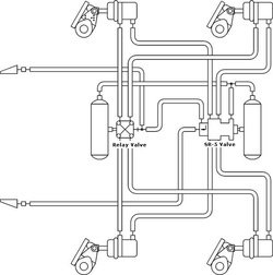
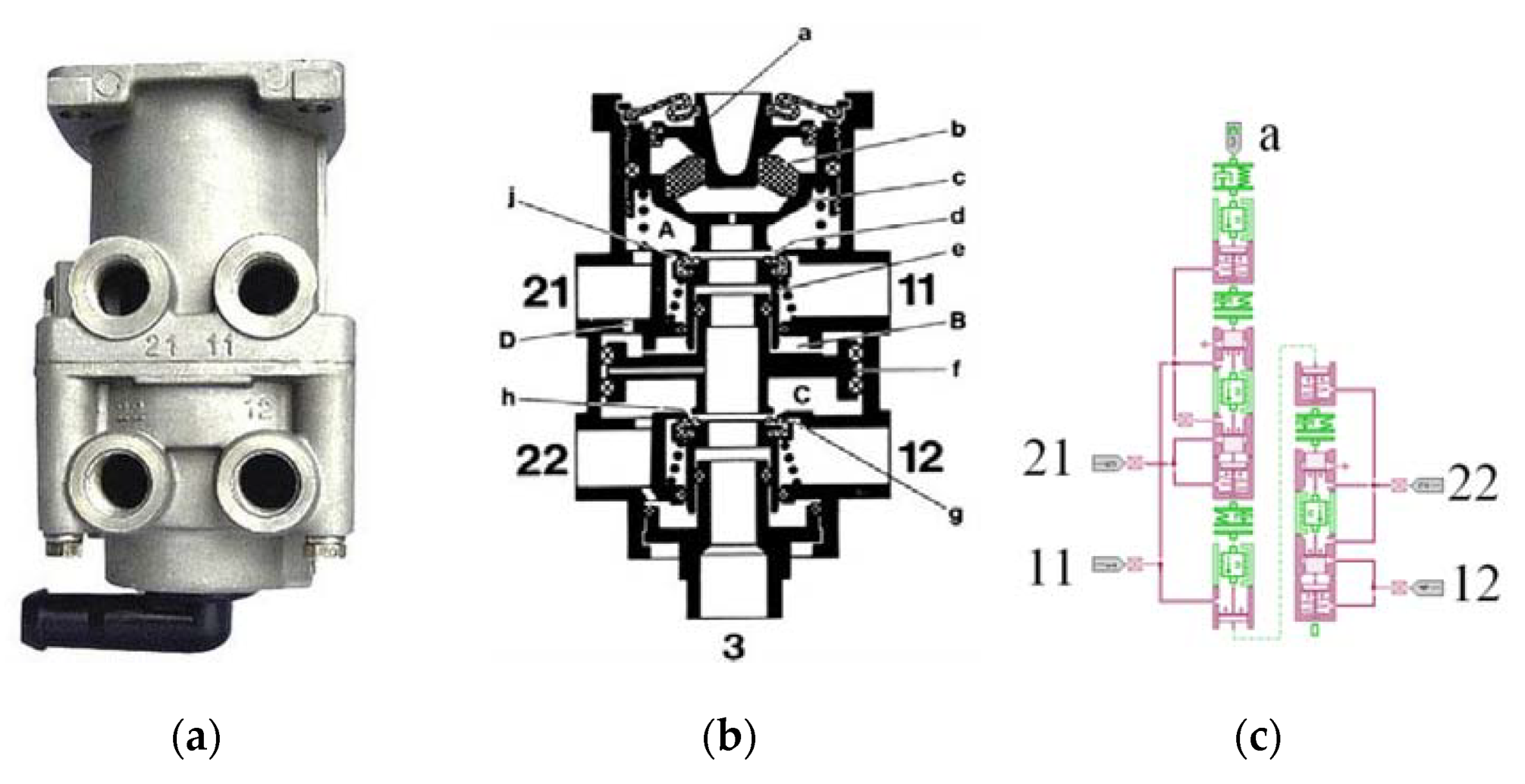
Bendix® R-12® & R-14® Relay Valves SD-03-1064
Fuse box diagram Chevrolet Silverado 2010-2013 Engine Control Module (ECM), Evaporative Emission (EVAP) Canister Purse Solenoid Valve (LU3), Mass Air Flow (MAF)/Intake Air Temperature (IAT) Sensor (LU3) 6. ITBC Fuse. 15A. Integrated Trailer Brake Control Module (JL1) 7. FRT WASH Fuse. 15A. Windshield Washer Fluid Pump. 8. O2-B SNSR Fuse. 10A
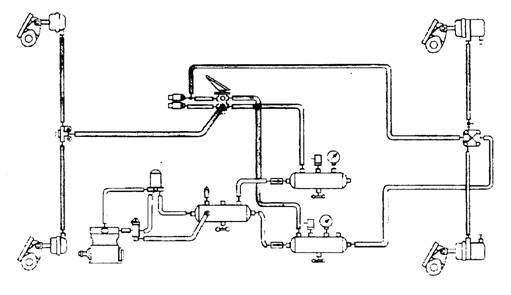
Sealco Commercial Vehicle Products - Air System Piping Diagrams
Air Brake Component Identifi cationAir Brake Component ... Air Brake Component Identifi cationAir Brake Component Identifi cation Specify genuine Bendix® replacement parts every time you service your air brake system. † All genuine Bendix replacement parts are manufactured to meet original OE specifications to guarantee quality, reliability, and proper operating performance.
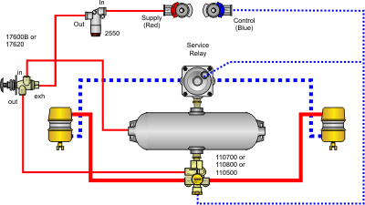
Piping diagrams: spring brake control for trailers - St ...
Basic Air Brake System Schematics - Total Truck Parts Typical 6 Wheel Air Brake System. These diagrams are provided for basic identification only. Always consult a professional technician to properly troubleshoot your system. Typical 10 Wheel Brake System. These diagrams are provided for basic identification only. Always consult a professional technician to properly troubleshoot your system.
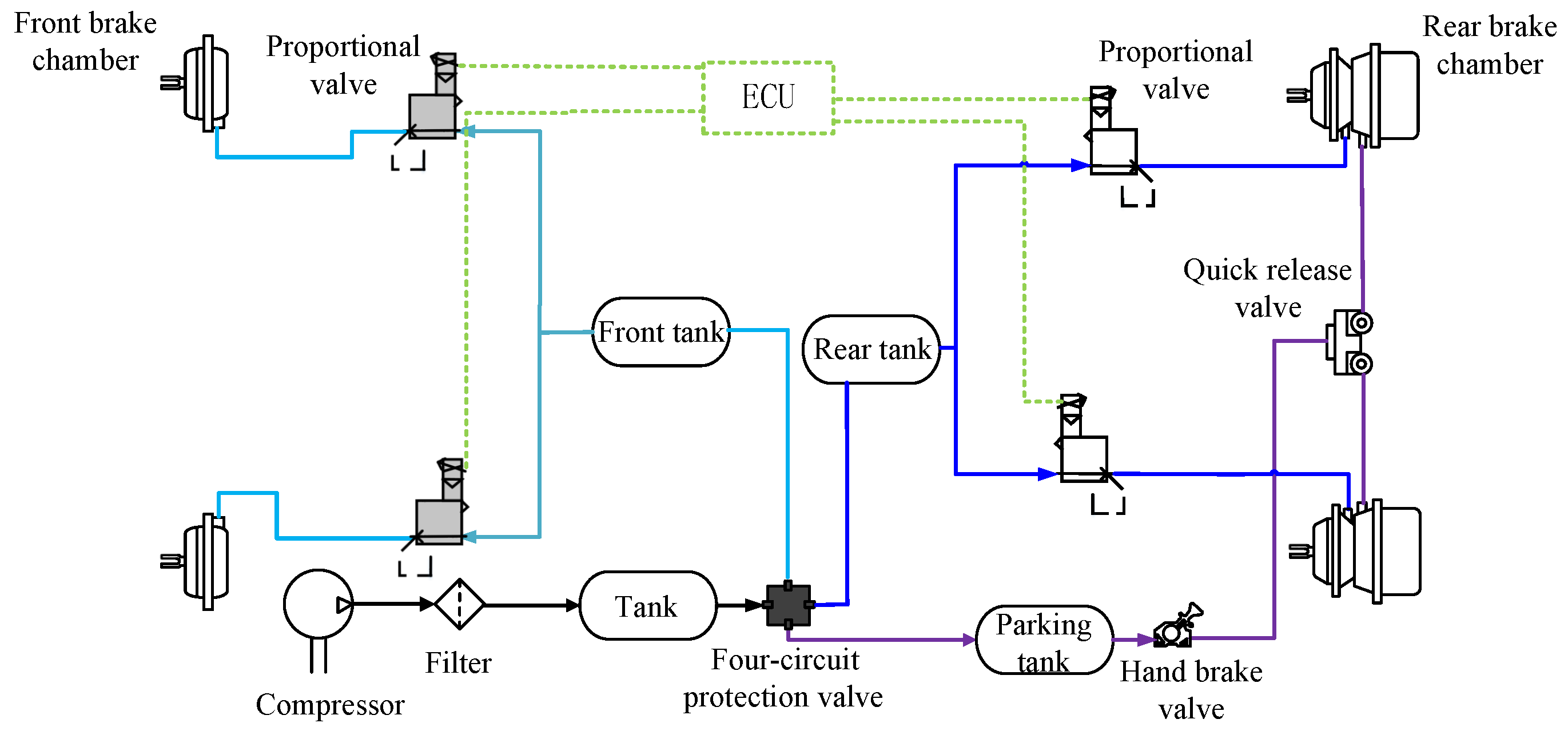
Processes | Free Full-Text | Gain-Scheduled Model Predictive ...
Bendix Foot Valve Diagram - schematron.org Brake Valves (Foot Valves) from Bendix Bendix Catalog Pages E-5, single circuit brake/foot valve for suspended pedal. Can you supply a air brake diagram for mack truck, the bendix valve pt no is n Answered by a Bendix X E 6 Dual Circuit Foot Brake Air Valve. air brake valves and electronic controls.
Meritor WABCO Air Brake Systems
Mini Cooper Parts Catalog - Mini Mania That’s where our Classic Mini Exploded Diagram Catalog comes in handy. These exploded views allow you to see where the parts go, what parts they're used with, and what they're called in case you don't know. Shop using our parts diagrams or by category below! 1959-1990 Mini Diagram Catalog Chapter 2 - Engine Chapter 3 - Clutch Chapter 4 - Transmission & Gearshift Chapter 5 …

Basic air brake system - SGI
PDF Westinghouse Brakes - Berkman Klein Center Schematic Diagram of Air Brake System on Vehicle in Application Position . Air Brake Plain T Valve a ph raph by Sheila which was uploaded on May 6th, 2013. Westinghouse Quick-action Triple Valve is a photograph by Sheila Terry which was uploaded on May 1 Ith, 2013. Title:
Truck/Tractor/Bus
Air Brake Handbook - suspensionspecialists.com DuraFlo596™ Air Compressor . 8, 9 E10 ™ Brake Valve . . . . . . . . 15 ... Components are introduced and shown with typical system diagrams to show where they are used. As new components are introduced and their function explained, they gradually build up to a complete functioning air brake system.
Air Brakes
Brake Master Cylinder - Function , Working , main parts ... Brake Master Cylinder – Function , Working , main parts and Diagram Brake master Cylinders : In automotive engineering, the master cylinder is a control device that converts non-hydraulic pressure (commonly from a driver’s foot) into hydraulic pressure. This device controls slave cylinders located at the other end of the hydraulic system.

A general layout of a truck air brake system. | Download ...
Motorcycle Air Shifter Kits and Parts - Schnitz Racing Air or Electric Shifter Kits allow quick shifts at the push of a button without the need to let off the throttle. Schnitz Racing has complete air shifter kits and air shifter brackets to make easy installation of any air shifter kit on nearly any motorcycle.
AIR BRAKE SYSTEM TROUBLESHOOTING
Air Brake Schematic Diagram - Quizlet Air compressor. This component produces air for the brake system. Powered by the vehicle's engine, the air compressor draws in air at normal pressure and forces it into a much smaller space, causing the pressure of the air to increase. This compressed air is a form of stored energy. Brake valve, foot or treadle valve.
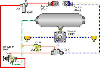
Sealco Commercial Vehicle Products - Air System Piping Diagrams
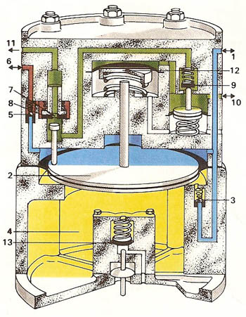
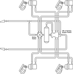
Air Brake Valve Diagram - schemacheck.com Air Brake Valve Diagram. Figure 12 - CMVSS Trailer air brake circuit, trailer spring brake control valve (Bendix SR-5), trailer parked. (Courtesy Allied Signal). On a straight truck, a spring brake control valve is added to the emergency brake air circuit. This gives the driver modulated control of the spring brakes.
Trailer Systems Truck System Tractor System
Bendix Parking Brake Valve Diagram | Valve, Diagram, Air brake Bendix Parking Brake Valve Diagram. D. Damion Weems. 72 followers. Air Brake. Diagram. More information.... More like this. Trailer Wiring Diagram. Electrical Wiring Diagram. Rv Solar Panels ... Diagram Of Air Brakes For A Truck and Car Brake Wiring Diagram #diagram #diagramtemplate - 18+ Diagram Of Air Brakes For A Truck .Diagram Of Air Brakes ...

A general layout of the air brake system in trucks | Download ...
International Air Brakes Series Air Brakes Series Welcome to the International® Air Brakes Series. The following DVD training series covers complete air brake fundamentals. It is designed to provide all the technical knowledge and skill necessary to diagnose and repair this brake system. This series is divided into six programs. The first program covers

BENDIX PP-3 TRAILER SUPPLY VALVE MANUAL Pdf Download | ManualsLib
PDF Air Brake System Troubleshooting I With the introduction of spring brakes, anti-compounding and 121 air brake systems, because a valve is leaking air out of its exhaust, does not mean the valve is at fault. If a spring brake is leaking from the the spring brake to the service brake side, that air will travel back up the service line and out the exhaust of the ...

Air Operated Power Brake System (Automobile)
Air Brake Manual - SGI The five main components of an "elementary" air brake system and their purposes are the compressor, reservoir, foot valve, brake chambers, and brake shoes and drums or brake rotors and pads.. You must have an Endorsement A specified on your licence to operate a vehicle equipped with an air brake system. The endorsement is not required when operating a Class 3 or 5 vehicle licensed as a ...

Schematic diagram of the modified air brake system of ...
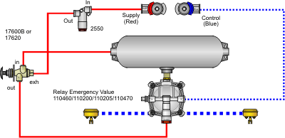
Sealco Commercial Vehicle Products - Air System Piping Diagrams
Electronics | Free Full-Text | Pneumatic ABS Modeling and ...

Archer Tower Printable Diagram Source | Trailer wiring ...

Relay valve - SGI
BODY BUILDER INSTRUCTIONS

Parking brake valve - Articulated Haulers Volvo A25B - Brake ...
Piping diagrams: spring brake control for trailers - St ...

Air Brake Relay Valve - Operation/Movements without Narration

Brake application - hand valve - SGI

http://www.truckt.com Air Brakes Anti-Compounding Theory
Dual-Circuit Air Brake Control System
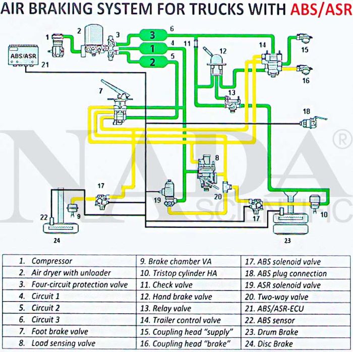
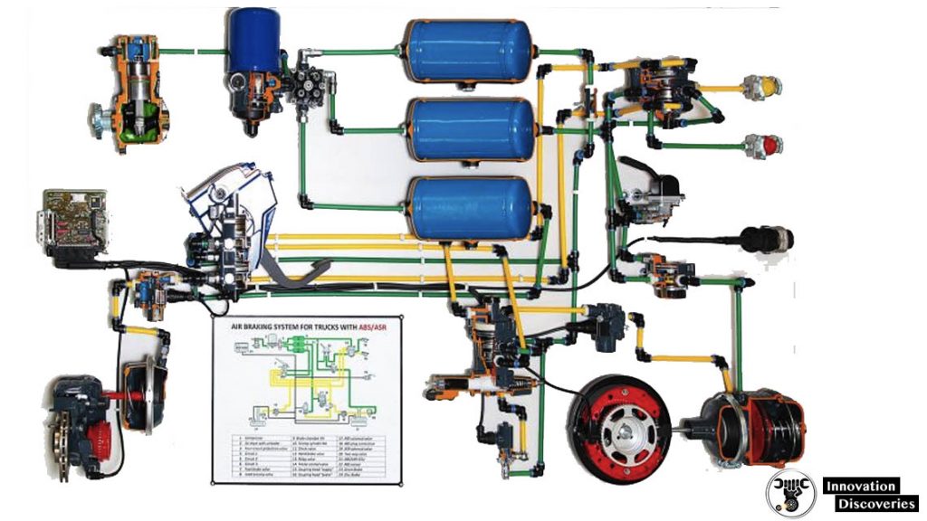
Air Braking System for Trucks with ABS / ASR, on Stand with ...
Dual Air Brake | Georgia Commercial Drivers Manual ...

Air Brake Parts for Buses and Trucks
How Air Brake System Works in Automobile? - Mechanical Booster
AIR BRAKE SYSTEM: COMPONENTS, WORKING PRINCIPLE, AND

Chapter 28 Truck Brake Systems. - ppt video online download

Fundamentals of Machine Tools


Comments
Post a Comment