39 impulse momentum diagram
How to draw Impulse momentum diagram - YouTube Description PDF Part I Review Unit Review Name Momentum and Impulse Momentum and Impulse A) 200. kg m/s B)50.0 kgm/s C) 20.0 kg m/s D) 12.5 kg m/s 1.A 5.00-kilogram block slides along a horizontal, frictionless surface at 10.0 meters per second for 4.00 seconds. The magnitude of the block's momentum is A) speed of the box B)mass of the contents of the box C) magnitude of the horizontal force applied to the box
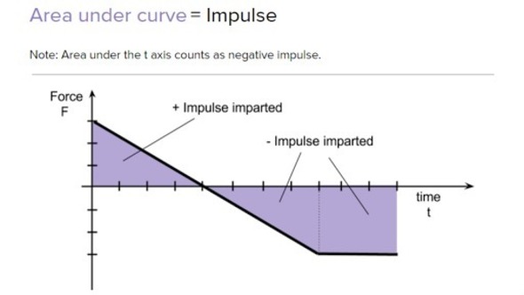
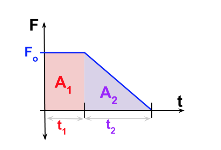
PDF TOPIC 1.3: MOMENTUM - Province of Manitoba the impulse. See diagram below: Force-Time Graph • Area A represents positive area (constant force) • Area B represents negative area (constant force) • Area C represents positive area (triangle) (constantly changing force) • Area D represents positive area (trapezoid) (constantly changing force) Student Activity

Impulse momentum diagram
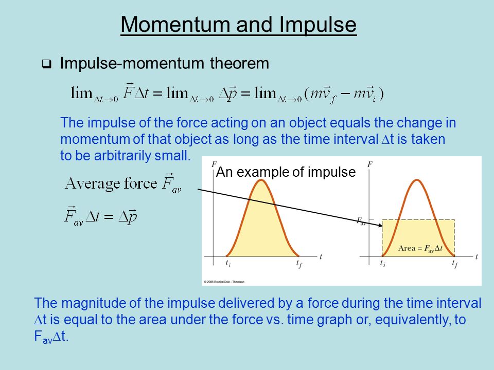
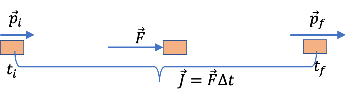
Impulse Formula with Examples - BYJUS Impulse is the big force acting for a very small interval of time. It is represented by J⃗ J→. Impulse Formula is articulated as. J=F×t. Where, Force applied is given as F; Time interval throughout which force is applied is given as t. Impulse can also be articulated as the rate of change of momentum. J=m×v. Where, Mass of the body is ... Impulse | Physics - Lumen Learning Figure 1 shows a graph of what an actual force looks like as a function of time for a ball bouncing off the floor. The area under the curve has units of momentum and is equal to the impulse or change in momentum between times t 1 and t 2. That area is equal to the area inside the rectangle bounded by F eff, t 1, and t 2. Thus the impulses and their effects are the same for both the actual and effective forces. AP Physics 1 Collisions: impulse and momentum Diagram ... impulse is equal to change in momentum inelastic collision A collision in which the colliding objects become distorted, generate heat, and possibly stick together.
Impulse momentum diagram. PDF Mr. Sault's Classroom - Mr. Sault's Thoughts The diagram below depicts the changes in velocity of a ball that undergoes a collision with a wall. Indicate which case (A or B) has the greatest change in velocity, greatest acceleration, greatest momentum change, and greatest impulse. Momentum Vector Diagrams: The Physics Teacher: Vol 58, No 9 Impulse-momentum diagrams were designed to help students understand the principle of conservation of momentum. They effectively show the magnitude of the momentum but are limited to only problems in one dimension. In this paper we will show a structured teaching method using momentum vector diagrams (MVD) as a tool. Momentum Change and Impulse - Physics Classroom The diagrams below depict the changes in velocity of the same ball. For each representation (vector diagram, velocity-time graph, and ticker tape pattern), indicate which case (A or B) has the greatest change in velocity, greatest acceleration, greatest momentum change, and greatest impulse. Support each answer. Impulse and momentum dodgeball example (video) - Khan Academy Impulse and momentum dodgeball example. Transcript. In this video, David shows how to solve for the impulse and force applied during a dodgeball collision using the impulse momentum relationship. Created by David SantoPietro.
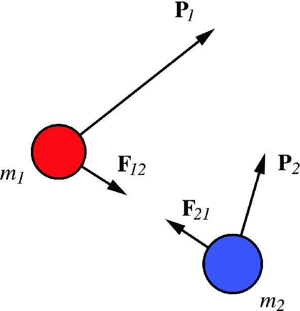
"Impulse-Momentum Diagrams" by David Rosengrant These representations include: pictures, free‐body diagrams, energy bar charts, electrical circuits, and, more recently, computer simulations and animations. However, instructors have limited choices when they want to help their students understand impulse and momentum. One of the only available options is the impulse‐momentum bar chart. Impulse-Momentum Diagrams: The Physics Teacher: Vol 49, No 1 One of the only available options is the impulse‐momentum bar chart. 6 The bar charts can effectively show the magnitude of the momentum as well as help students understand conservation of momentum, but they do not easily show the actual direction. This paper highlights a new representation instructors can use to help their students with momentum and impulse—the impulse‐momentum diagram (IMD). PDF Impulse and Momentum •Principle of Impulse and Momentum. •In accordance with the established coordinate system, formulate scalar component equations by either resolving the vector components of F from the free-body diagram •Every force acting on the particle's free-body diagram will create an impulse, even though some of these forces will do no work. ERIC - EJ913078 - Impulse-Momentum Diagrams, Physics ... Impulse-Momentum Diagrams. Rosengrant, David. Physics Teacher, v49 n1 p36-39 Jan 2011. Multiple representations are a valuable tool to help students learn and understand physics concepts. Furthermore, representations help students learn how to think and act like real scientists.
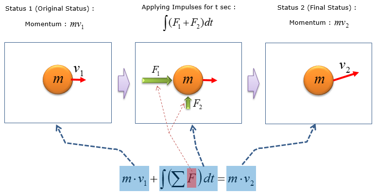
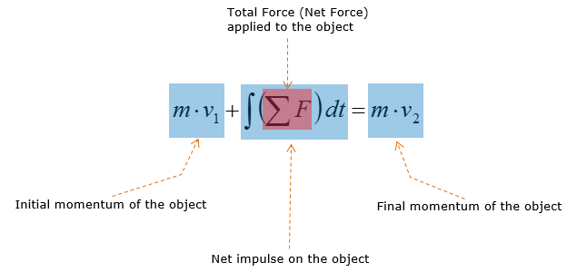
Momentum, Impulse & Collisions: Ballistic Pendulum, An ... Momentum, Impulse & Collisions: Ballistic Pendulum, An Explanation - YouTube. Impulse-Momentum Diagrams | Request PDF - ResearchGate Impulse-momentum diagrams were designed to help students understand the principle of conservation of momentum. They effectively show the magnitude of the momentum but are limited to only problems ... PDF Principle of Linear Impulse and Momentum The two momentum diagrams indicate direction and magnitude of the particle's initial and final momentum, mv 1 and mv 2. The impulse diagram is similar to a free body diagram, but includes the time duration of the forces acting on the particle. The particle's initial momentum plus the sum of all the impulses applied from t 1 to t 2 PDF Physics 1120: Momentum and Impulse Solutions Physics 1120: Momentum and Impulse Solutions 1. The diagrams below are graphs of Force in kiloNewtons versus time in milliseconds for the motion of a 5kg block moving to the right at 4.0 m/s. (a) What is the magnitude and direction of the impulse acting on the block in each case?
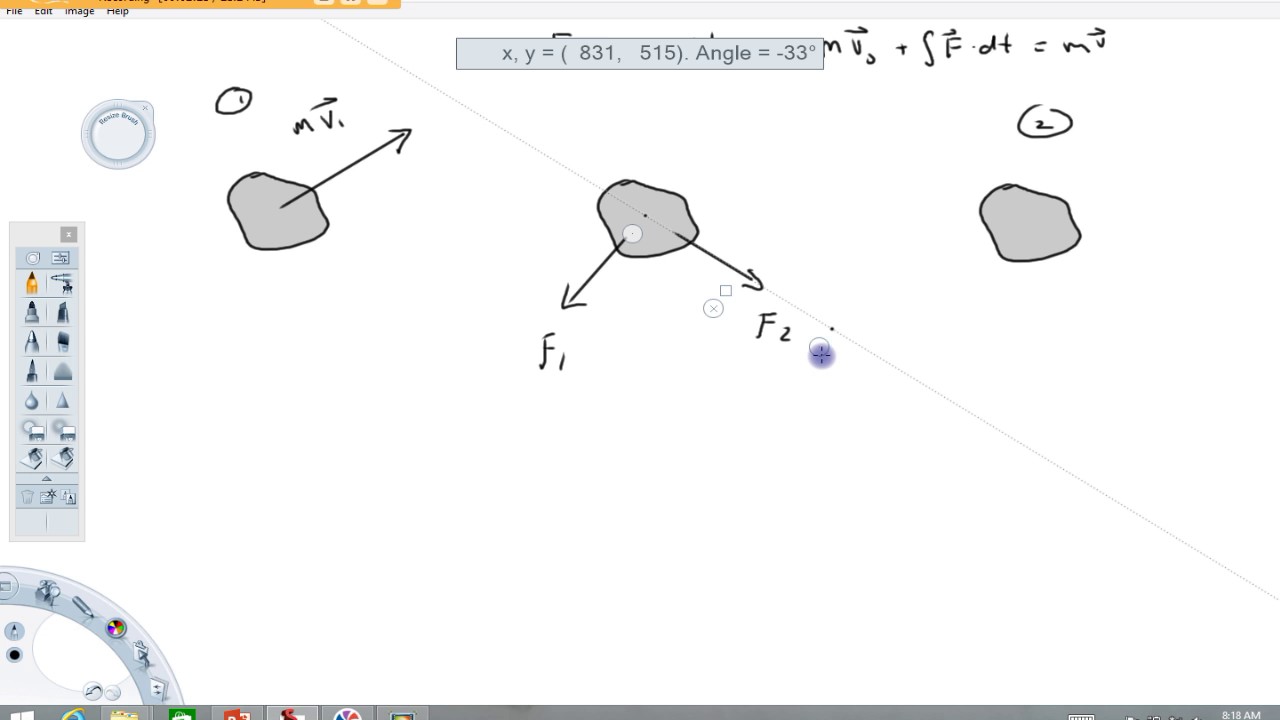
Dynamics Tutorial - Impulse-Momentum method: A slider under the influence of two external forces
PDF Preliminary Study of Impulse-Momentum Diagrams new option, Impulse-Momentum Diagrams (IMDs) created by Rosengrant. We describe these diagrams in the next section. IMPULSE-MOMENTUM DIAGRAMS Momentum is the product of a scalar quantity (mass) and vector quantity (velocity). Thus a representation for momentum must adhere to these two conditions. IMDs do this by combining motion
ShareTechnote
A tennis player strikes the tennis ball with her racket ... We construct the impulse-momentum diagrams for the ball as follows: 2. [ m ( v x) 1 + ∫ t 1 t 2 Σ F x d t = m ( v x) 2] − 2 / 1 6 3 2. 2 ( 5 0) + R x ( 0. 0 2) = 2 / 1 6 3 2. 2 ( 7 0 cos 1 5 ∘) \left [m\left (v_ {x}\right)_ {1}+\int_ {t_ {1}}^ {t_ {2}} \Sigma F_ {x} d t=m\left (v_ {x}\right)_ {2}\right] \quad-\frac {2 / 16} {32.2} (50)+R_ {x} (0.

Momentum and Impulse Practice Problems Diagram | Quizlet
Impulse Turbine - an overview | ScienceDirect Topics Figure 9-9 shows a diagram of a single-stage impulse turbine. The static pressure decreases in the nozzle with a corresponding increase in the absolute velocity. The absolute velocity is then reduced in the rotor; however, the static pressure and the relative velocity remain constant.
Impulse-Momentum Diagrams | Semantic Scholar
Impulse and Momentum - Summary - The Physics Hypertextbook Impulse-Momentum Theorem. The impulse-momentum theorem states that the change in momentum of an object equals the impulse applied to it. J = ∆p. If mass is constant, then… F∆t = m∆v. If mass is changing, then… F dt = m dv + v dm. The impulse-momentum theorem is logically equivalent to Newton's second law of motion (the force law). Units

Impulse and Momentum
1-2011 Impulse-Momentum Diagrams - Kennesaw State University Momentum is the product of an object's mass and its veloc-ity, written mathematically as shown in Eq. (1): p = mv. (1) Momentum is the product of a scalar quantity (mass) and a vector quantity (velocity). Thus, a representation for momen-tum must take both of these quantities into account. Impulse-momentum diagrams do this by combining motion diagrams
Impulse, Momentum, and Collisions | SpringerLink
PDF AP Physics 1- Momentum, Impulse, and Collisions Practice ... diagram below. Rank the four carts from least to greatest in terms of: 1. Initial momentum, 2. Impulse applied, 3. Final momentum, 4. Final velocity (1.ABDC, 2.DACB, 3.ADBC, 4.DCBA) Q13. A 1-kg box accelerates from rest in a straight line across a frictionless surface for 20 s as depicted in the force vs. time graph to the upper right.
Chapter 6: Momentum and Collisions Momentum and Impulse ...
Impulse-Momentum Diagrams - NASA/ADS Impulse-Momentum Diagrams. Multiple representations are a valuable tool to help students learn and understand physics concepts. Furthermore, representations help students learn how to think and act like real scientists. 2 These representations include: pictures, free-body diagrams, 3 energy bar charts, 4 electrical circuits, and, more recently, ...

2.5 Impulse | Momentum and impulse | Siyavula
Momentum Bar Charts (IF Charts, IFF Charts) - Physics! Blog! The diagrams in the examples above have already been annotated, so we're ready for the next step. In each of the example situations, let's assume that there's no outside net force to transfer momentum into or out of the system. In other words, momentum is conserved in those three situations.
Video: Physics: AP Physics 1 review of Momentum and Impulse ...
Impulse-Momentum Diagrams | Semantic Scholar This paper highlights a new representation instructors can use to help their students with momentum and impulse—the impulse‐momentum diagram (IMD). Multiple representations are a valuable tool to help students learn and understand physics concepts.1 Furthermore, representations help students learn how to think and act like real scientists.2 ...
Momentum Bar Charts (IF Charts, IFF Charts) – Physics! Blog!
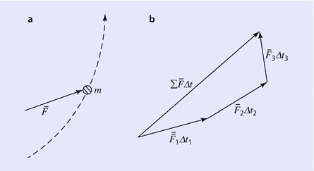
PDF Kinetics of Particles: Work and Energy Impulse-Momentum Diagram The three scalar impulse-momentum eqns are completely independent In the middle drawing linear impulses due to all external forces should be included (except for those forces whose magnitudes are negligible) Impulse-Momentum diagrams can also show the components ME101 - Division III Kaustubh Dasgupta 6
Impulse and Change in Momentum
IB DP Physics 2.4 - Momentum and impulse Question Bank SL ... impulse is force × time / force is rate of change of momentum; time to come to rest is longer for car B; force experienced by car B is less (so less likely to be damaged);
Impulse-Momentum Diagrams | Semantic Scholar
16.2 Momentum Diagrams | Week 5: Momentum and Impulse ... Similarly, if these two objects collide and they're moving, we actually don't know which way those objects will end up moving. And so what we'd again like to do in our final state, after this collision, is to represent the velocities by, again, vectors. So this is V1 final and this is V2 final.
![[2015] Dynamics 19: Principle of Linear Impulse and Momentum [with closed caption]](https://i.ytimg.com/vi/spaurCJzktQ/maxresdefault.jpg)
[2015] Dynamics 19: Principle of Linear Impulse and Momentum [with closed caption]
AP Physics 1 Collisions: impulse and momentum Diagram ... impulse is equal to change in momentum inelastic collision A collision in which the colliding objects become distorted, generate heat, and possibly stick together.

2.5 Impulse | Momentum and impulse | Siyavula
Impulse | Physics - Lumen Learning Figure 1 shows a graph of what an actual force looks like as a function of time for a ball bouncing off the floor. The area under the curve has units of momentum and is equal to the impulse or change in momentum between times t 1 and t 2. That area is equal to the area inside the rectangle bounded by F eff, t 1, and t 2. Thus the impulses and their effects are the same for both the actual and effective forces.
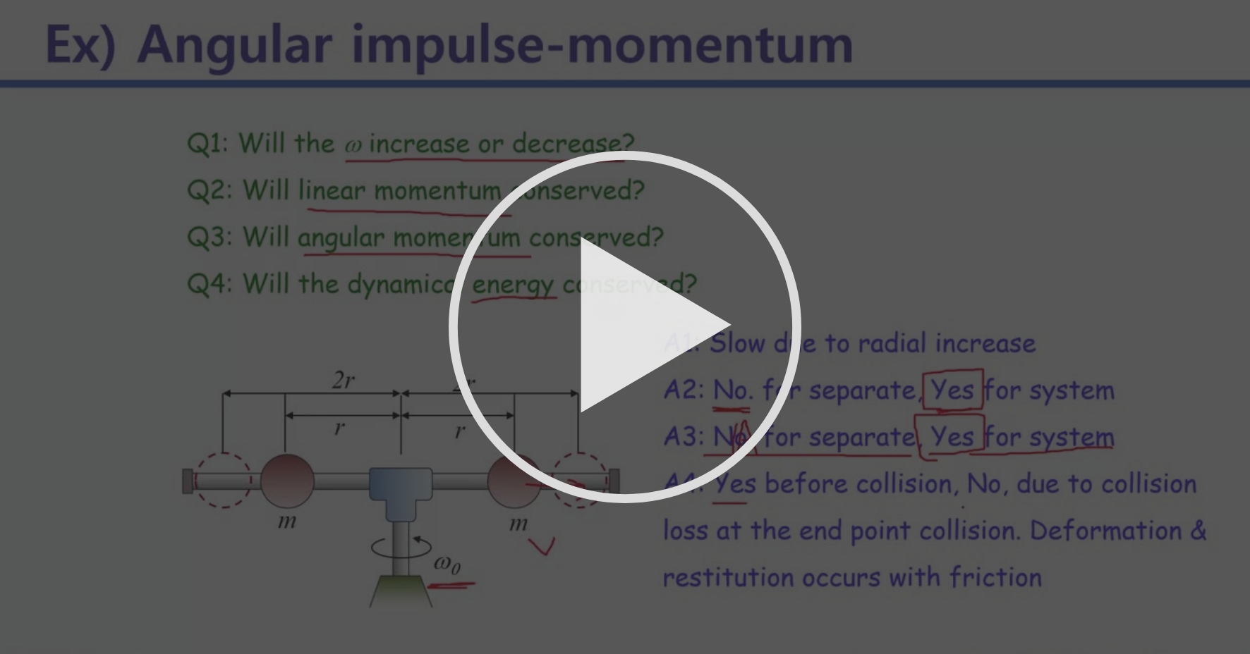
Angular impulse-momentum, example 2 - 4-1 Week | Coursera
Impulse Formula with Examples - BYJUS Impulse is the big force acting for a very small interval of time. It is represented by J⃗ J→. Impulse Formula is articulated as. J=F×t. Where, Force applied is given as F; Time interval throughout which force is applied is given as t. Impulse can also be articulated as the rate of change of momentum. J=m×v. Where, Mass of the body is ...
Conservation Laws Momentum and Impulse Momentum A quantity

2.6_part 2 Impulse and momentum of rod type rigid body
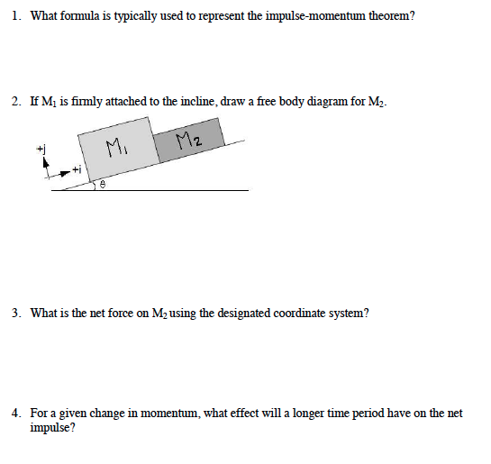
Solved What formula is typically used to represent the ...
1 Impulse – Momentum Lab
Impulse review (article) | Laws of motion | Khan Academy

PPT - Impulse and Momentum PowerPoint Presentation, free ...
Impulse And Momentum
Momentum in Baseball by Ellie Chen
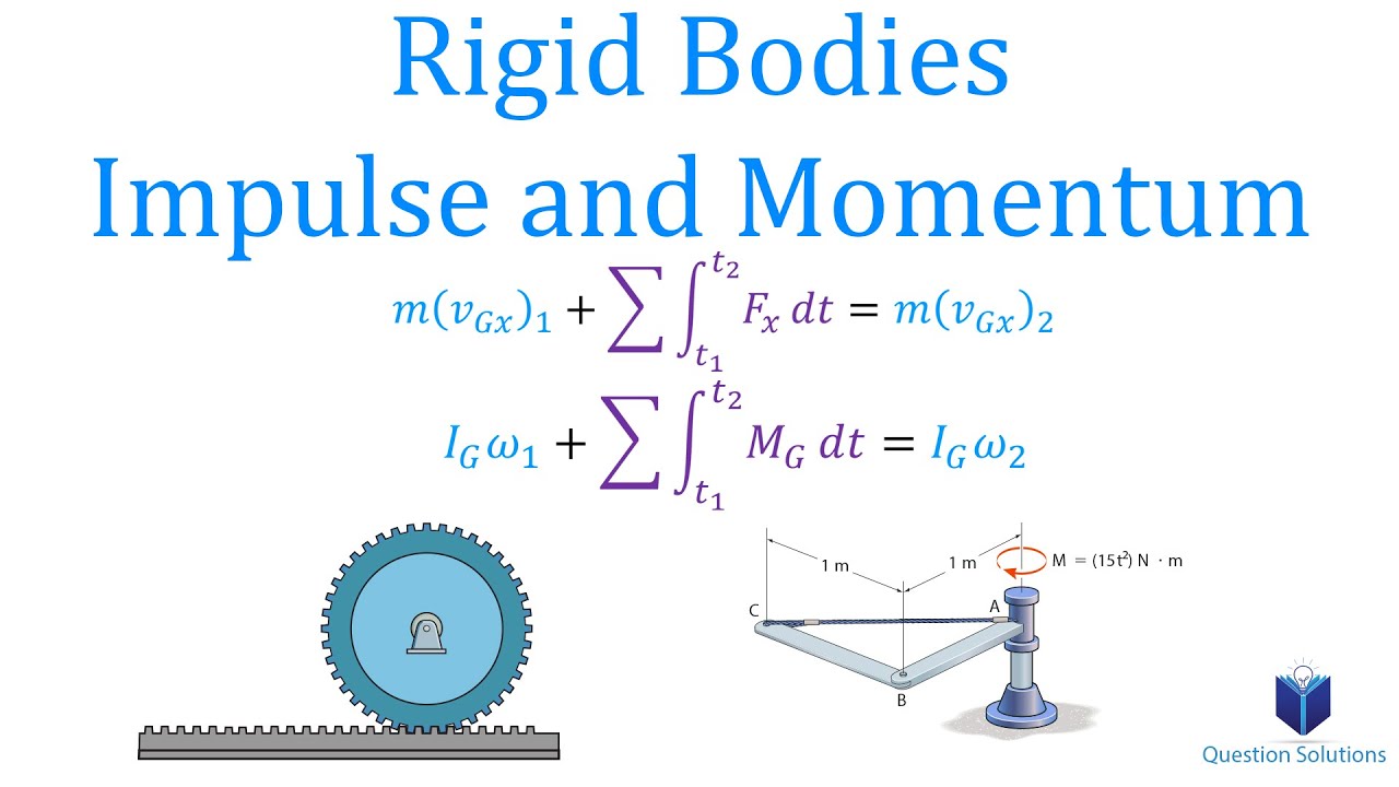
Rigid Bodies Impulse and Momentum Dynamics (Learn to solve any question)

Question to Identify Students' difficulties related to ...
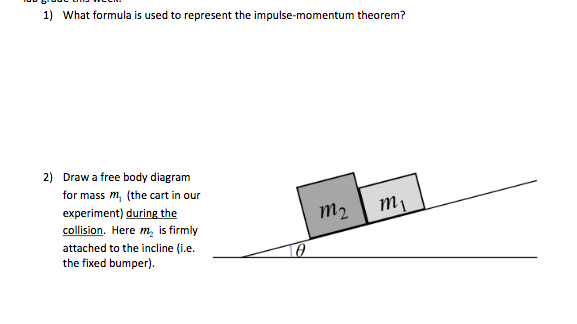
Solved 1) What formula is used to represent the | Chegg.com
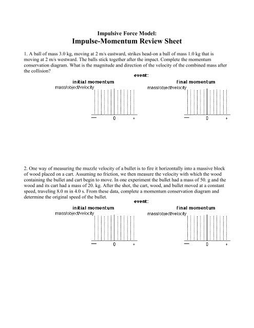
Impulse-Momentum Review Sheet - Modeling Physics

Determining the takeoff velocity in the vertical jump using ...

Kinetics - Particle impulse and momentum
impulse and momentum WS1
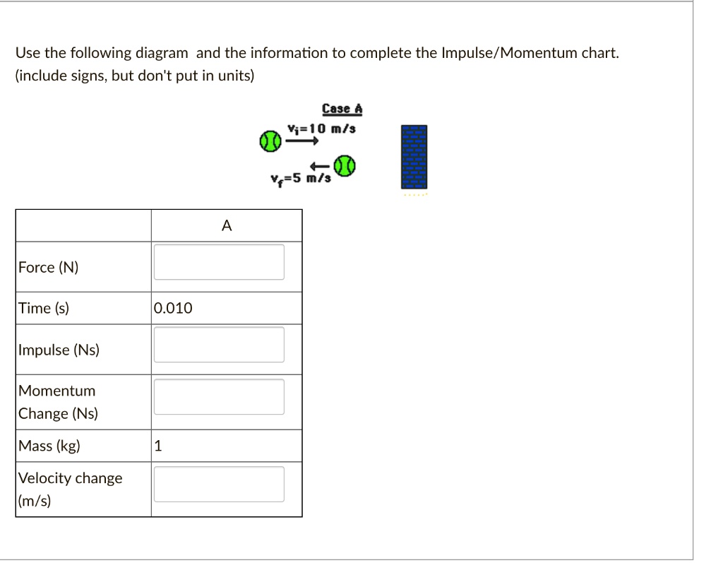
SOLVED:Use the following diagram and the information to ...
ShareTechnote

1.3.5. Impulse - Force time graphs - PGS Physics
How to draw Impulse momentum diagram
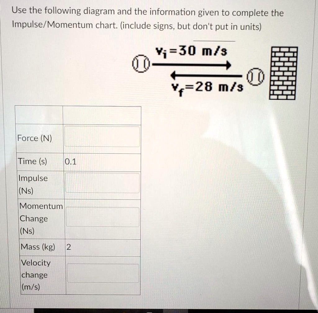
SOLVED:Use the following diagram and the information given to ...
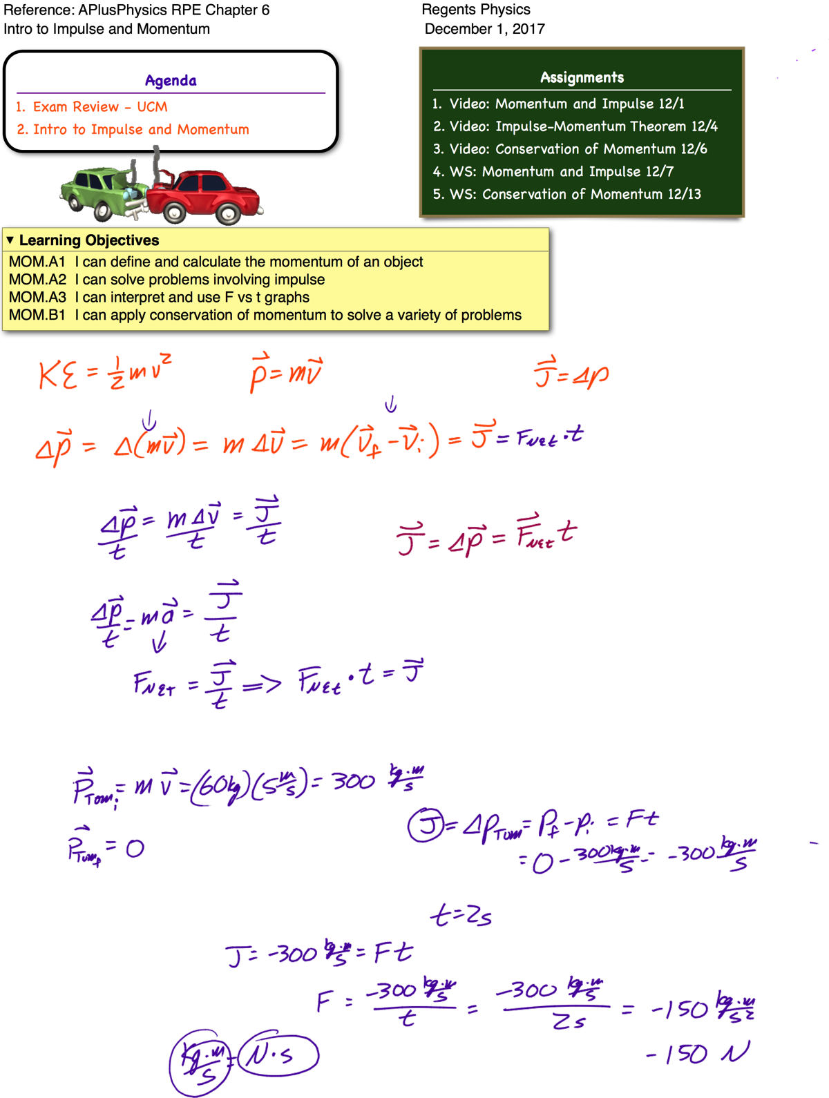
Intro to Impulse and Momentum - Regents Physics

The impulse-momentum equation: E-Learning Platform for IFM
Impulse and Momentum | SpringerLink
Momentum Change and Impulse


Comments
Post a Comment