40 rf modulator hookup diagram
Intellivision Service Manual (Model 2609) ICs. RF modulator and the power transformer are provided in Section 7. Schematic diagrams for the PCB Power Supply and PCB LOGIC are also provided in Section 7. Figure 1-2 is a func- tional block diagram Of the Master Component. The system on the 01 two proc.sors which time-share a 14-bit bidirec— tional The central processing unit (CPU ... Conditioning A/V Signals for RF Modulatio | Maxim Integrated Block diagram of A/V signal conditioning to drive an RF modulator. Table 1. Audio Requirements from ITU-R BT.470-6 Table 2. Video Requirements from ITU-R BT.470-6 Note 1: See Figure 3 of ITU-R BT.470-6. Some of these requirements depend on the source.
AM Modulator and 50W RF Output Stage [] Diagram Guide The output stage is built using discrete transistors and guarantees a 50 Ω output impedance with low DC offset. The complete circuit can deliver a constant amplitude output signal of up to 2.5 Vpp (unmodulated) for frequencies ranging to over 20 MHz. If the signal is not modulated, the maximum amplitude can be increased somewhat.

Rf modulator hookup diagram
Fm Transmitter Block Diagram And Explanation Of Each Block ... Block diagram of a low level FM broadcast transmitter is shown in figure. Frequency Modulation is the process in which the frequency of the carrier signal is varied by the modulating signal while the amplitude remains constant. The exciter section contains the carrier oscillator reactance modulator and the buffer amplifier. Satellite and TV wiring - iRV2 Forums Hookup would be - sat antenna to receiver, receiver component output to RF modulator, modulator out to Windgard switch which then directs sat signal to selected TV. Moisheh, I hope this is at all helpful because I am a bit confused when you say Monaco wired the TV antenna through the sat receiver - not sure what this means. Information, Owner's Manual and Support for the CRF907 RF ... Information on the RCA CRF907 RF Modulator. CRF907 Owner's Manual. Warranty Card. Wiring Diagram. Connecting the RF Modulator to Your TV: Use an audio/video cable to connect your video source (like a DVD player or VCR) to the RF modulator. Match the colors of your audio/video cable to the colors of the jacks on your video source.
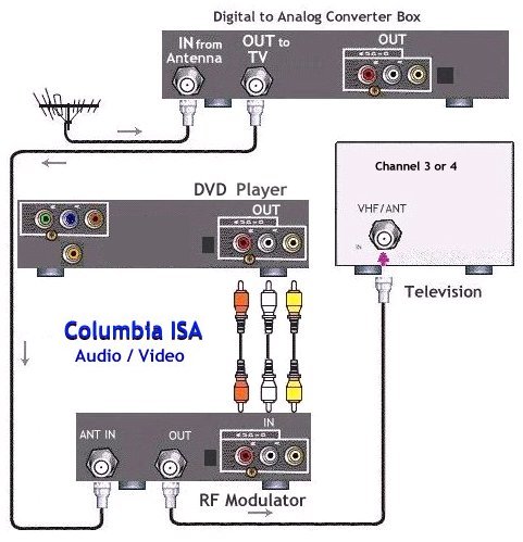
Rf modulator hookup diagram. Rf modulator hookup | Rollingtrans Rf modulator hookup - Want to meet eligible single woman who share your zest for life? Indeed, for those who've tried and failed to find the right man offline, rapport can provide. Join the leader in mutual relations services and find a date today. Join and search! Men looking for a man - Women looking for a man. RF TVLink Modulator - AV To RF Converter With IR Extender RF TVLink Modulator - AV to RF Converter with IR Extender - Control DSTV / Multichoice Decoder Explora 3 from remote room. This RF TV Link Modulator is used to enable you to change channels from a remote room. satellite tv wiring diagrams - Wiring Diagram and ... Dvd vcr tv satellite rf modulator dss dbs single dual lnb wiring diagrams connect hdtv dish network installation steps cable diagram dvr hd prewiring your home for ideal distribution digital kapek solution and Wiring Diagrams Dvd Vcr Tv Satellite Rf Modulator Multiswitches For Dss Dbs Single Satellite Dual Lnb Wiring Diagrams Connect Tv […] columbiaisa - dvd_rf_modulator - Google Search First, plug your cable TV/VCR output into the cable input connection(ANT IN) of the RF modulator and then the DVD player's 3 RCA A/V cables (yellow, red, white) into the RF modulator's A/V inputs...
The Basics of Home Theater: Sample Wiring Diagrams The first diagram is the simplest, showing a DVD player attached to a TV that does not have any audio/video inputs (which people with older TV's will often encounter); in this case, the TV provides the speakers (or speaker, as it will mostly likely not have stereo sound). This diagram includes an alternate diagram adding a VCR and switchbox. How to Connect a RF Modulator - HowStuffWorks Plug the modulator's electricity cord into a power outlet. Turn both the modulator and the stereo or TV on to check that you connected them properly [source: JASCO ]. Connecting to another VHF Input Source Connecting your RF modulator to both a TV set and a VCR, DVD or cable box is easy. Dish Network Hopper 3 Wiring Diagram Dish hopper wiring diagram rf modulator. A wiring diagram is a streamlined standard pictorial representation of an electric circuit. Start date jan 22 2019. If you want hopper joey you ll have to give up your old receivers that are on the same account. Hookup wiring diagrams dvd vcr tv satellite rf modulator dish dvr 625 wiring diagram wiring ... RF Signal Generator : 8 Steps (with Pictures) - Instructables The RF signal generator is a must to have tool when playing with radio receivers. It is used to tune a resonant circuits and adjust the gain of different RF stages. Very useful feature of the RF Signal generator is its modulation capability. If it can modulate the frequency amplitude or frequency makes it non replaceable tool for RF design works.
columbiaisa - video_connect_diagrams - Google Search How to Hookup an Audio Video Receiver Cable Connection Diagrams 1.) Connect DVD player to TV - Older TV, has no RCA jacks. RF modulator required. 2.) Connect DVD player and VCR to TV - Older TV,... The Basics of Home Theater: Sample Wiring Diagram The A/V switch let him connect up to four A/V sources (VCR, DVD, game console, ...) and even switch between them using his existing device remotes. The output of the switch is composite video and stereo analog audio, which can be connected directly to an RF modulator and on to the TV. What does rf modulator do? Do I need it? Where to buy This RF Modulator has 4 HDMi inputs and Closed Caption. The platform provides 5 full RF carrier outputs for generating channels from content ingested through the ASI input. Encoding in either MPEG2 or H.264 is provided for 4 crystal clear video streams up to 1080p 60 each HDMI to coax , HDMI to IPTV ,HDMI over coax Features DVD VCR hookup to TV with RF modulator - GEOCITIES.ws Hookup Diagram shows DVD and VCR connection to RF modulator and to TV. RF Modulator Recoton DVD647, available at major electronics retailers: The RF Modulator is ideal for TVs not equipped with an A/V jack. It's used for connecting a DVD player, video game system, camcorder, or other A/V component that does not have an RF (coaxial) output to a ...
circuit design - Logic reversal of RF Receiver? - Electrical Engineering Stack Exchange
Rf Modulator Wiring Diagram - 4K Wallpapers Review Video modulator circuit video dvd vcr hookup to tv with rf modulator digital cable box using rf modulator ... Rf Modulator Wiring Diagram Dvb T De 4 Canales De Tv Modulador Para El Proyector China Modulador Dvb T. Previous Next. Suggested Wallpapers: How To Use Rf Modulator, Related Gallery: ...
.jpg.7efeab1c8813ed269c4575584376b92d.jpg)
RF-modulator - Installation Help and Accessories - CCTVForum.com
Connect older TV to DVD, VCR & Digital Cable Box using RF ... The answer to the above questions is a little black box that has been around for years called an RF modulator (Radio Frequency Modulator). The function of an RF modulator is simple. The RF modulator converts the video (and/or audio) output of a DVD player (or camcorder or video game) into a channel 3/4 signal that is compatible with a TV's ...
How to connect hookup a DVD player
How to Hook Up an RF Modulator With DirecTV | Techwalla Step 1 Plug one end of the component cables into the "Audio/Video OUT" ports on the rear of the DirecTV receiver. Video of the Day Step 2 Connect the other end of the cables into the matching AV ports on the modulator. Step 3

remote control - What do I need for a basic RF circuit? - Electrical Engineering Stack Exchange
How to install a RF Modulator - YouTube How to install a RF Modulator

Basic RF Oscillator - Circuit Scheme
Hybrid Solo Hub Wiring Diagram - magnifico Dss dbs single satellite dual lnb dvd vcr tv rf modulator vip 722k wiring diagram dishtv connection diagrams best how to a recorder directv basic direct dish network installation steps electrical cable converting winegard trav ler antenna work full vizio xbox 360 hdtv keystone montana 5th wheel forum dvr hd regular setting up your new mydish ...

TIVO TV DVD Switcher Hookup Diagram
Dish Network Home Wiring Diagram / Diagram Diagram For ... Dish hopper wiring diagram rf modulator. Otherwise, the arrangement will not work as it should be. Installation dish network satellite wiring diagram from yugteatr.org effectively read a electrical wiring diagram, one has to find out how the components within the method operate. Articleabove dish network vipk wiring diagram published by admin.
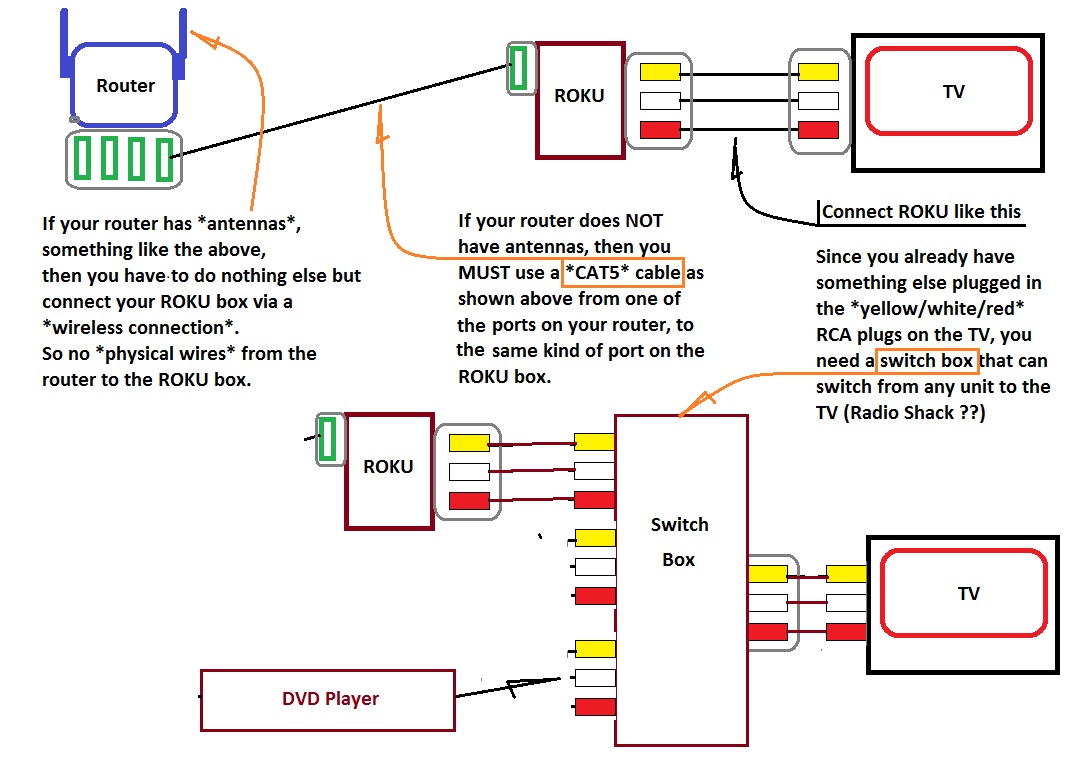
How to hook up ROKU box (to old tv, have cable) (connect, Time Warner) - Consumer Electronics ...
Fixing a noisy rf modulator - Page 1 - EEVblog Re: Fixing a noisy rf modulator. These very simple modulators are just a VHF or UHF oscillator that is amplitude modulated by the composite video signal. Crude, but they worked. As the modulator is an Amplitude Modulated oscillator it is important that the power supply to it is not too noisy. The fault with your Sega could actually be outside ...

April | 2017 | OneTubeRadio.com
Jensen Vx7020a Wiring Diagram - schematron.org This is the wiring diagram for the RF modulator. PDF CDX Installation Free Download PDF The serious radio will not connect to my Jensen VX online at schematron.org caution during installation to avoid causing a short circuit. wiring diagram carefully and make certain all connections are.

Memotech MTX 512 - Video Hardware
Wiring Diagrams for your Entertainment System Click here to see this wiring diagram Wiring Instructions: Connect one end of the Composite Red (Right)/White (Left)/Yellow (Video) cable to the DVD connector labeled Composite, Audio/Video, Output or TV and the other end to a RF Modulator.

communication - RF Module Not Working - Electrical Engineering Stack Exchange
Rf transmitter and receiver circuit diagram pdf ... Rf transmitter and receiver circuit diagram pdf RF Circuits schematic information RF Circuits about June 2011 for RF Circuits Adjust your FM receiver to the frequency of your transmitter. Select Mono reception mode. Adjust POT1, POT2, POT3, POT4 and POT5 to minimum. Connect a TAPE or CD player Left (L) channel to the encoder. Play a sound track.
PRO2 RFMX3IR 3 INPUT RF MODULATOR WITH IR PRO2 - Radio Parts - Electronics & Components
Fm Transmitter Block Diagram And Explanation Of Each Block This block diagram of a radio transmitter in a communication system is very simple and basic. FM broadcast the maximum modulating frequency is 15 kHz. There are two important functions of RF amplifier. This form of FM detector block is widely used within ICs. 2 To reject image frequency signal.
Video to RF Modulator - RF circuit circuits - ElShem.com
Information, Owner's Manual and Support for the CRF907 RF ... Information on the RCA CRF907 RF Modulator. CRF907 Owner's Manual. Warranty Card. Wiring Diagram. Connecting the RF Modulator to Your TV: Use an audio/video cable to connect your video source (like a DVD player or VCR) to the RF modulator. Match the colors of your audio/video cable to the colors of the jacks on your video source.
![A QUICK REVIEW - Essential Guide to RF and Wireless, The [Book]](https://www.oreilly.com/library/view/essential-guide-to/0130259624/0130259624_ch03lev1sec7_image01.gif)
A QUICK REVIEW - Essential Guide to RF and Wireless, The [Book]
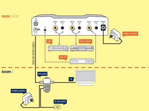
Satellite and TV wiring - iRV2 Forums Hookup would be - sat antenna to receiver, receiver component output to RF modulator, modulator out to Windgard switch which then directs sat signal to selected TV. Moisheh, I hope this is at all helpful because I am a bit confused when you say Monaco wired the TV antenna through the sat receiver - not sure what this means.

Hookup Diagram RF Modulator DVD TV UK
Fm Transmitter Block Diagram And Explanation Of Each Block ... Block diagram of a low level FM broadcast transmitter is shown in figure. Frequency Modulation is the process in which the frequency of the carrier signal is varied by the modulating signal while the amplitude remains constant. The exciter section contains the carrier oscillator reactance modulator and the buffer amplifier.

Patent US7486743 - Device and method of measuring frequency domain response in RF modulator ...
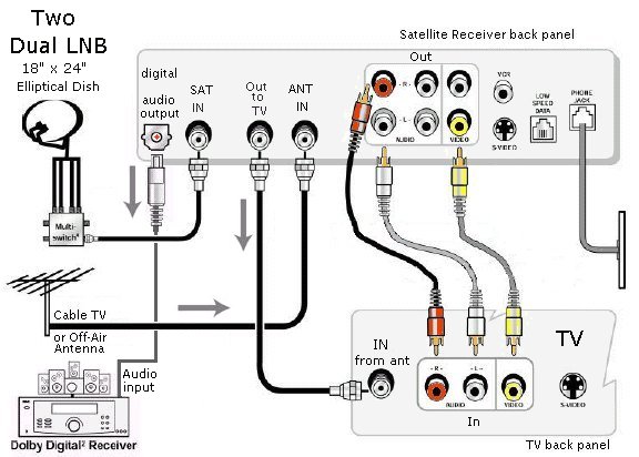
Multiswitches for DSS DBS single satellite dual LNB


Comments
Post a Comment